| Quantity | 3+ units | 10+ units | 30+ units | 50+ units | More |
|---|---|---|---|---|---|
| Price /Unit | $25.79 | $25.27 | $24.48 | $23.42 | Contact US |
 The Latest DDCS Version4.1 4 Axis Independent CNC Offline Controller Machine and Manual Pulse Generator DDPMG
$329.72
The Latest DDCS Version4.1 4 Axis Independent CNC Offline Controller Machine and Manual Pulse Generator DDPMG
$329.72
 The Latest DDCS Version4.1 3 Axis Independent CNC Offline Controller Machine and Manual Pulse Generator DDMPG
$310.28
The Latest DDCS Version4.1 3 Axis Independent CNC Offline Controller Machine and Manual Pulse Generator DDMPG
$310.28
 DDCS-V4.1 4-Axis Standalone Motion Controller Offline Controller Support 3 Axis/4Axis USB CNC Controller Interface
$296.11
DDCS-V4.1 4-Axis Standalone Motion Controller Offline Controller Support 3 Axis/4Axis USB CNC Controller Interface
$296.11
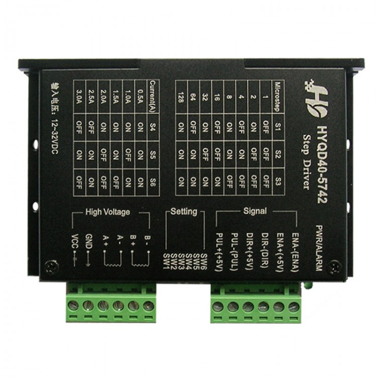
57 42 Stepper Motor Driver DC30V 3A 128 Subdivision HYQD40-H5742 Controller
Introduction:
HYQD40-5742 is a two step a professional motor drive. Can achieve positive control, through the 3 dial switch to select 8 gear subdivision control (1,2,4,8, 16, 32, 64128), the 3 bit code switch to select 6 gear current control (0.5A, 1A, 1.5A, 1.8A, 2.5A, 3A). Suitable for driving 57, 42 phase, four phase hybrid stepping motor. Can achieve low vibration, low noise, high speed drive motor.
Product features
- The power supply has the anti reverse function
- The current is selected by a dial switch
- Adopts high-speed Optocoupler
- High integration and high reliability
- Anti high frequency interference
- Maximum voltage DC 40V
- Eight segment adjustable
- Semi-automatic flow
Input terminal:
The input signal has three paths, they are: step pulse signal CP+, CP-; direction level signal DIR+, DIR- and offline signal EN+, EN-. Input signal interface has two kinds of connection: the user can according to need to adopt common anode or common cathode connection. (hereinafter to common connection method as an example)
Common anode connection: the CP+, DIR+, EN+ connected to the power supply control system, if the power supply is +5V can directly access, if this power is greater than +5V, it shall be external plus a current limiting resistor R, which provides drive current is 8 - 15mA to drive internal coupling. Pulse input signal through the CP- access, the direction of the signal through the DIR- access, enabling signal via the EN- access.
Note: EN is not connected, EN efficient when the rotor is in free state (offline), then can be manually rotated motor shaft, do your adjustment. Manual adjustment is completed, then the EN is set to an invalid state, to continue to automatic control
Motor wiring:
2 Phase 4 line, 6 line, 8 line motor wiring
The four line direct access; six line is not connected with the intermediate tap, the two connected together (intermediate tap according to resistance determination); eight lines can be used in parallel or series connection, parallel connection for the high current.
System wiring diagram:
Note: please disconnect the power supply wiring, electrical wiring should pay attention not to phase error, phase to phase short circuit, so as not to damage the drive.
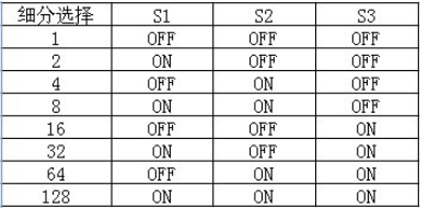
The fine fraction set
Fine fraction is to drive plate on the dial switch settings, depending on the options table data set (the best setting in the absence of power). Subdivision back stepping motor step angle is calculated according to the following procedures: step motor step angle = inherent / fine fraction. Such as: a natural step angle is 1.8 ° of the stepper motor in the 4 subdivision step angle is 1.8 ° /4=0.45 °
The driving plate dial switch 1, 2, 3 respectively corresponding to S1, S2, S3.
Subdivision table:
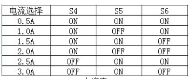
The drive plate adjustable current range of 0.5A~2.8A, the specific data refer to the current selection table. The drive plate dial switch 4, 5, 6 respectively corresponding to S4, S5, S6.
Current table:
Off-line function (enable):
Open the off-line function, motor rotor is not locked state, can easily rotate, when the input pulse signal does not respond, close this signal after receiving the pulse signal normal operation of motor.
Instructions: Click here
Package included:
- 1 xStepper Motor Driver