| Quantity | 3+ units | 10+ units | 30+ units | 50+ units | More |
|---|---|---|---|---|---|
| Price /Unit | $13.25 | $12.98 | $12.57 | $12.03 | Contact US |
 Waveshare ESP32-S3 Development Board ESP32-S3R2 GEEK 1.14-inch LCD ST7789 for USB Dongle Support 2.4GHz WiFi BLE5
$17.68
Waveshare ESP32-S3 Development Board ESP32-S3R2 GEEK 1.14-inch LCD ST7789 for USB Dongle Support 2.4GHz WiFi BLE5
$17.68
 M5Stack M5GO IoT Starter Kit V2.7 High Performance IoT Start Development Kit ESP32 2-inch IPS Screen for Arduino
$96.24
M5Stack M5GO IoT Starter Kit V2.7 High Performance IoT Start Development Kit ESP32 2-inch IPS Screen for Arduino
$96.24
 M5Stack Glass2 Unit 1.51-inch Transparent OLED Extended Screen Unit for SSD1309 Driver Solution
$34.22
M5Stack Glass2 Unit 1.51-inch Transparent OLED Extended Screen Unit for SSD1309 Driver Solution
$34.22
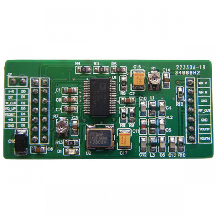
AD9850 DDS Signal Generator Module Circuit Diagram
Features :
- 2 sine wave and 2 square wave output
- AD9850: 0-40MHz
- After the 20-30MHz frequency harmonics increases, the waveform will be less and less clean
- Square Wave: 0-1MHz
- Low-pass filter with 70MHz, so the waveform better than SN
- Parallel and serial data input can be selected via a jumper
- DA produced the benchmark pin (PIN12) leads for easy adjustment to do the magnitude of the output waveform Application
- Comparator reference input voltage generated by the variable resistor, the resistor can be adjusted duty cycle square wave of different
- Active AD9850 125MHz crystal oscillator modules
- 100% Brand New


")


