| Quantity | 3+ units | 10+ units | 30+ units | 50+ units | More |
|---|---|---|---|---|---|
| Price /Unit | $12.13 | $11.88 | $11.51 | $11.02 | Contact US |
 AXera PI Zero Module 5MP AI-ISP Camera Module Designed with SoC Chip AX620Q+SC450AI Image Sensor
$67.98
AXera PI Zero Module 5MP AI-ISP Camera Module Designed with SoC Chip AX620Q+SC450AI Image Sensor
$67.98
 0.5-inch 1024X768 OLED Driver Board High Quality Circuit Board for V760A-5 Wearable Head Mounted Display
$40.24
0.5-inch 1024X768 OLED Driver Board High Quality Circuit Board for V760A-5 Wearable Head Mounted Display
$40.24
 1PCS SFP+ Dual Mode Optical Module Small Form-factor Pluggable Transceiver Support 10Gbps Transmission with LC Interface
$26.09
1PCS SFP+ Dual Mode Optical Module Small Form-factor Pluggable Transceiver Support 10Gbps Transmission with LC Interface
$26.09
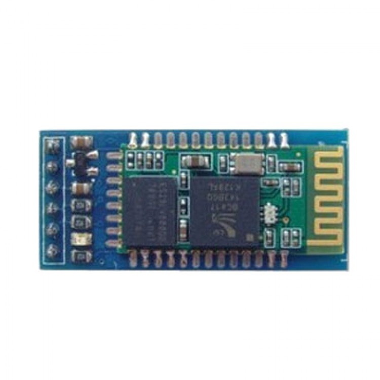
Arduino Bluetooth Module Slave Wireless Serial Port With Baseboard
Instruction:
- Industrial serial port bluetooth, Drop-in replacement for wired serial connections, transparent usage. You can use it simply for a serial port replacement to establish connection between MCU and GPS, PC to your embedded project and etc.
- Computer and peripheral devices
- GPS receiver
- Industrial control
- MCU projects
- Default serail port setting : 9600, N, 8, 1
- Pairing code : 1234
- Running in slave role: Pair with BT dongle and master module
Usage
- Coupled Mode: Two modules will establish communication automatically when powered.
- PC hosted mode: Pair the module with bluetooth dongle directly as virtual serial.
- Bluetooth protocal : Bluetooth Specification v2.0+EDR
- Frequency : 2.4GHz ISM band
- Modulation : GFSK(Gaussian Frequency Shift Keying)
- Emission power : <=4dBm, Class 2
- Sensitivity : <=-84dBm at 0.1% BER
- Speed : Asynchronous: 2.1Mbps(Max) / 160 kbps, Synchronous: 1Mbps/1Mbps
- Security : Authentication and encryption
- Profiles : Bluetooth serial port
- CSR chip : Bluetooth v2.0
- Wave band : 2.4GHz-2.8GHz, ISM Band
- Protocol : Bluetooth V2.0
- Power Class : (+6dbm)
- Reception sensitivity: -85dBm
- Voltage : 3.3 (2.7V-4.2V)
- Current : Paring - 35mA, Connected - 8mA
- Temperature : -40~ +105 Degrees Celsius
- User defined Baud rate : 4800, 9600, 19200, 38400, 57600, 115200, 230400,460800,921600 ,1382400.
- Dimension : 26.9mm*13mm*2.2mm
Pin definition :
- PIO8 connects with LED cathodea with 470ohm series resistor in between. LED NEGATIVE connects to ground. It is used to indicate the module state. After powered on, flashing intervals differ in different states.
- PIO9 is used to control LED indicating paring. It will be steady on when paring is successful.
- PIO11, module state switching pin. HIGH -> response to AT command; LOW or floating -> regular work status.
- With build-in reset circuit, reset is completed automatically after powered on.
- Steps to set to MASTER:
- Set PIO11 HIGH with a 10K resistor in between.
- Power on, module comes into AT Command Response Status
- Open HyperTerminal or other serial tool, set the baud rate 38400, 8 data bits, 1 stop bit, no parity bit, no Flow
Control
- Via serial port, send characters "AT + ROLE = 1 r n",if successful, return "OK r n", where r n is carriage return.
- Set PIO11 LOW, re-power, then in Master state, automatically search for slave module and connect.