| Quantity | 3+ units | 10+ units | 30+ units | 50+ units | More |
|---|---|---|---|---|---|
| Price /Unit | $45.96 | $45.02 | $43.62 | $41.74 | Contact US |
 The Latest DDCS Version4.1 4 Axis Independent CNC Offline Controller Machine and Manual Pulse Generator DDPMG
$329.72
The Latest DDCS Version4.1 4 Axis Independent CNC Offline Controller Machine and Manual Pulse Generator DDPMG
$329.72
 The Latest DDCS Version4.1 3 Axis Independent CNC Offline Controller Machine and Manual Pulse Generator DDMPG
$310.28
The Latest DDCS Version4.1 3 Axis Independent CNC Offline Controller Machine and Manual Pulse Generator DDMPG
$310.28
 DDCS-V4.1 4-Axis Standalone Motion Controller Offline Controller Support 3 Axis/4Axis USB CNC Controller Interface
$296.11
DDCS-V4.1 4-Axis Standalone Motion Controller Offline Controller Support 3 Axis/4Axis USB CNC Controller Interface
$296.11
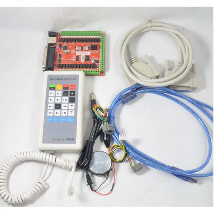
CNC 6 Axis USB LPT Mach3 Breakout Board Kit w/ Manual Control Box Handwheel for Controlling Stepper Motor
Description:
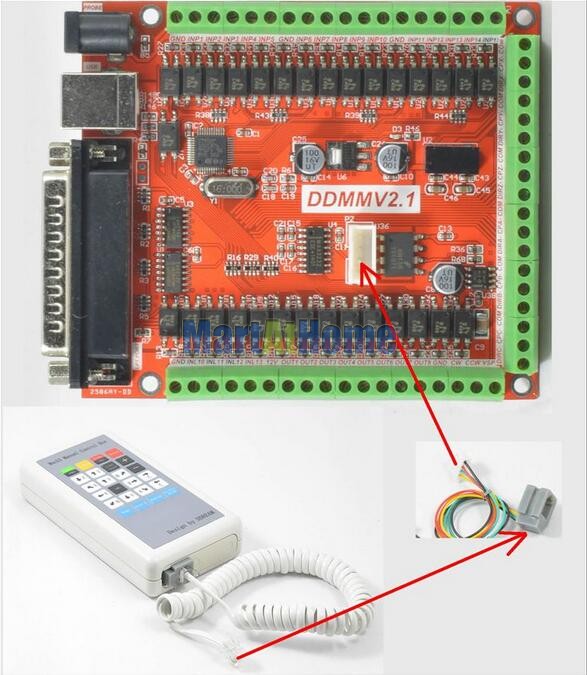
DDMMV2.1 is a CNC system based mach3 which name is short for “Digital Dream Multiple input Mach3 card Version 2.1”. This card is designed by our Studio You do not need to add other Hardware,and you can complete the signal conversion from the G-code to the movement of the stepper motor drive control. You should use both parallel port and USB port at the same time. This card is compatible with most stepper drives and servo drives. And it is perfect weapon to replace mach3 parallel interface board.
Requirements of Computer:
Basic Configuration:
- CPU: 1GHz
- Memory: 512MB
- 500MB Available disk space
- USB 2.0 5) LPT port
Recommended configuration:
- CPU: 2GHz Dual Core
- Memory: 2GB
- 1G Available disk space
- USB 2.0
- L PT port
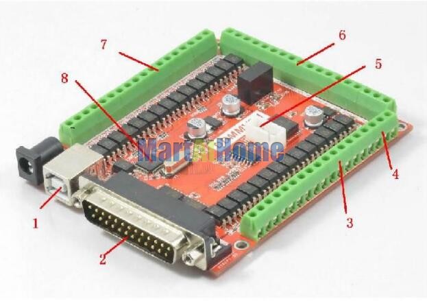
1. USB communication interface and power supply for the board
2. LPT port for stepper driver signal.
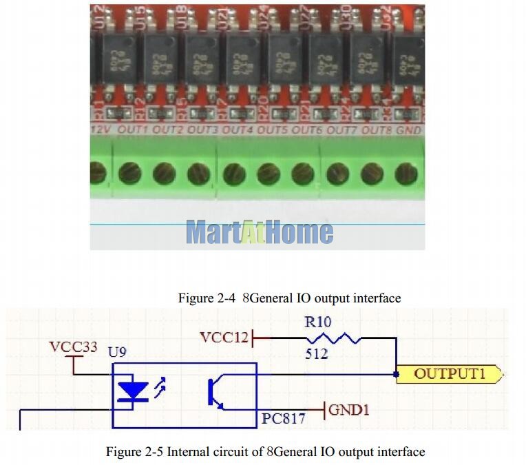
3. 8 IO outputs, opto-isolated
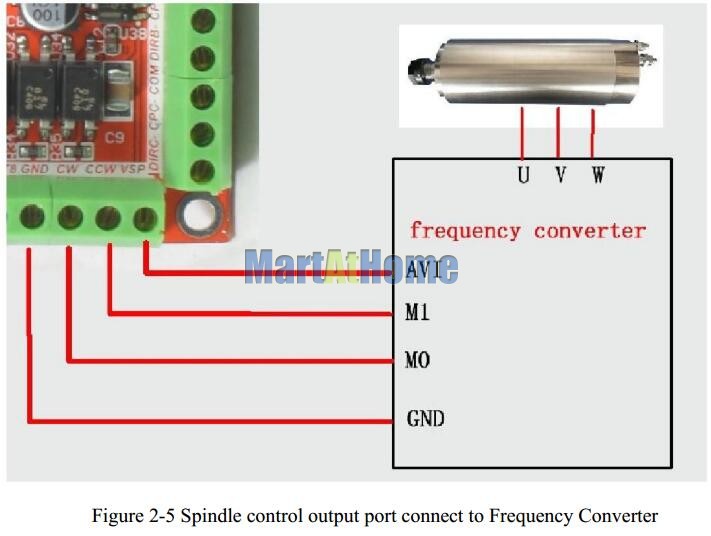
4. Spindle outputs signal;
5. Hand control box port;
6. 6 axis stepper driver signal output
7. 15 IO input, opto-isolated, It Can be configured to limit the emergency stop and other functions.
8. Use STM32 chip as a Master
Electrical parameters:
A. Operating voltage of input interface: 12V;
B. Operating voltage of output interface: 12V;
C. stepper motor control signal output voltage: 5V;
NOTE: The marked as “USB” is Power input and communication interface, you should connected correctly.
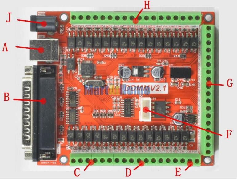
A) USB PORT. This interface is connected to the computer through a USB line. You can use the software mach3 to control this board, Note that you should use a USB2.0 cable with shielding and ferrite core, and cable length should be not more than 2 meters. This USB port not only provides power to the board, but also manages output & input port, hand control box interface and spindle control port.
B) LPT port. LPT port should be connected to parallel port of PC.LPT port only manages 6 axis stepper motor driver.
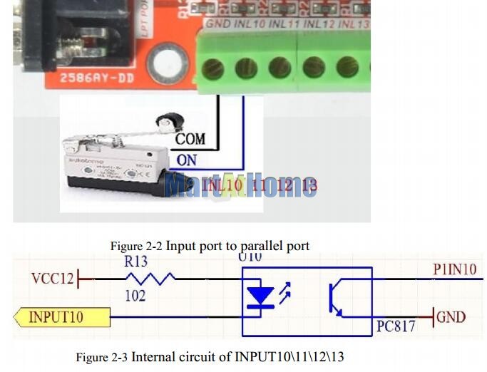
C) Input port to parallel port. There are input10\11\12\13 of parallel port. Wiring methods see as Figure2-2, you can link a Micro Switch to GND and INLX (X can be 10 11 12 13). Internal circuits of INPUT10\11\12\13
D) 8 General IO output interface, have a current drive capability within 5MA, defined as 12V O1, O2, O3, O4, O5,. O6, O7, O8, GND from left to right.
F) Hand control box port, RS232 port, wiring methods sees as Figure 2-6. The function of hand control box see as next Section
G) 6-axis stepper motor control signal output, defined as DIR-\CP-\COM. They are negative direction, negative pulse and positive common. These ports are common positive connection. This board does not support the common negative connection. Wiring method refer to Figure 2-6.This card doesn’t have EN signal, most drives on sale should not connected to the EN signal. It is defined as X \ Y \ Z \ A \ B channel from top to bottom, Wire methods see as Figure 2-6. COM connects to both SP+ and DIR+ of Driver; CP- connects to SP- of Driver; DIR- connects to DIR- of Driver.
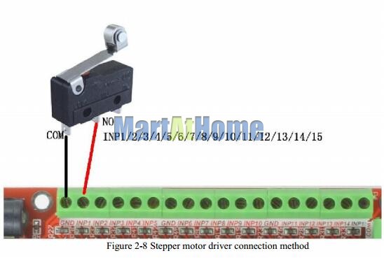
H) General INPUT PORT from USB, IN1-15, see as Figure 2-8,it is defined as GND, INP01, INP02, INP03, INP04, INP05, GND, INP06, INP07, INP08, INP09, INP10. GND. INP11, INP12, INP13, INP14 and INP15 from left to right, the interface uses opto-isolated, using common negative input, GND is used as the common Port. These input port is Managed by USB port. Wiring methods see as Figure 2-8.
J ) PROBE input port. This port is connected to PROBE, it’s something used to tool setting. Wire method see as Figure 2-9

Package contents:
- 1 x Board +USBIO expansion board
- 1 x Manual Control Box
- 1 x Paralleling Cable
- 1 x USB Cable