| Quantity | 3+ units | 10+ units | 30+ units | 50+ units | More |
|---|---|---|---|---|---|
| Price /Unit | $80.41 | $78.77 | $76.31 | $73.02 | Contact US |
 The Latest DDCS Version4.1 4 Axis Independent CNC Offline Controller Machine and Manual Pulse Generator DDPMG
$329.72
The Latest DDCS Version4.1 4 Axis Independent CNC Offline Controller Machine and Manual Pulse Generator DDPMG
$329.72
 The Latest DDCS Version4.1 3 Axis Independent CNC Offline Controller Machine and Manual Pulse Generator DDMPG
$310.28
The Latest DDCS Version4.1 3 Axis Independent CNC Offline Controller Machine and Manual Pulse Generator DDMPG
$310.28
 DDCS-V4.1 4-Axis Standalone Motion Controller Offline Controller Support 3 Axis/4Axis USB CNC Controller Interface
$296.11
DDCS-V4.1 4-Axis Standalone Motion Controller Offline Controller Support 3 Axis/4Axis USB CNC Controller Interface
$296.11
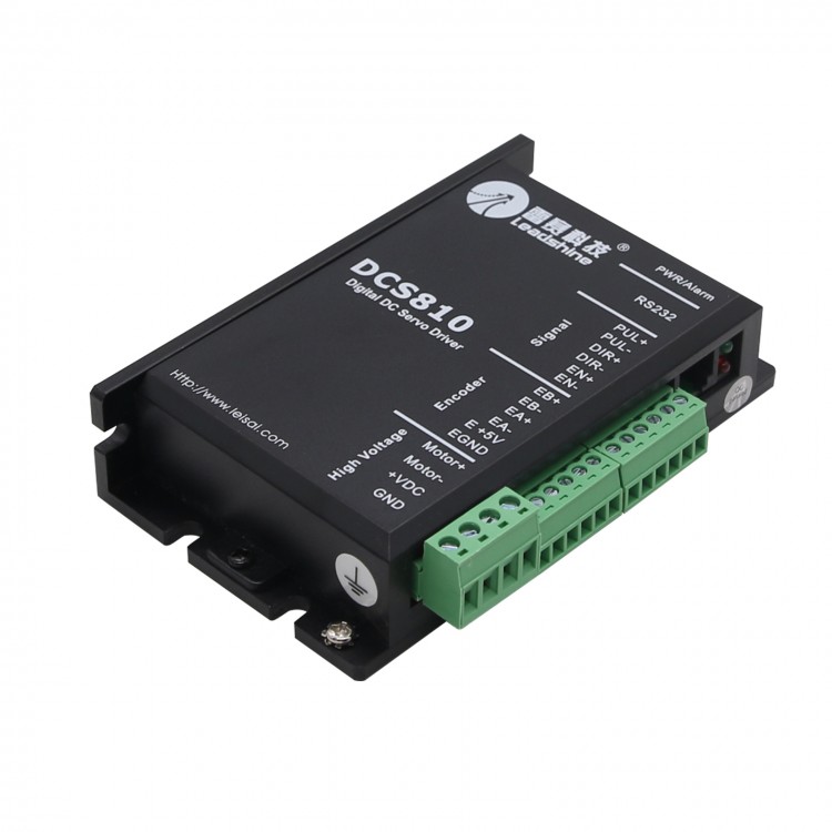
Leadshine DCS810 Leadshine Digital DC Servo Drive Driver Controller 80VDC/20A 400W DC
|
Parameters |
DCS810 |
|||
|
Min. |
Typical |
Max. |
Unit |
|
|
Peak output current |
0 |
- |
20 |
A |
|
Supply voltage |
+18 |
- |
+80 |
VDC |
|
Logic signal current |
7 |
10 |
15 |
mA |
|
Pulse input frequency |
0 |
- |
500 |
KHz |
|
Isolation resistance |
500 |
|
|
Mohm |
|
Current provided to encoder |
|
|
50 |
mA |
General information: