| Quantity | 3+ units | 10+ units | 30+ units | 50+ units | More |
|---|---|---|---|---|---|
| Price /Unit | $271.71 | $266.16 | $257.84 | $246.75 | Contact US |
 The Latest DDCS Version4.1 4 Axis Independent CNC Offline Controller Machine and Manual Pulse Generator DDPMG
$329.72
The Latest DDCS Version4.1 4 Axis Independent CNC Offline Controller Machine and Manual Pulse Generator DDPMG
$329.72
 The Latest DDCS Version4.1 3 Axis Independent CNC Offline Controller Machine and Manual Pulse Generator DDMPG
$310.28
The Latest DDCS Version4.1 3 Axis Independent CNC Offline Controller Machine and Manual Pulse Generator DDMPG
$310.28
 DDCS-V4.1 4-Axis Standalone Motion Controller Offline Controller Support 3 Axis/4Axis USB CNC Controller Interface
$296.11
DDCS-V4.1 4-Axis Standalone Motion Controller Offline Controller Support 3 Axis/4Axis USB CNC Controller Interface
$296.11
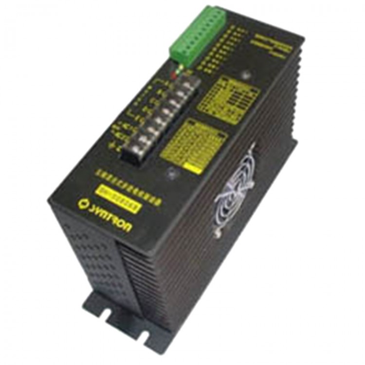
SH-50806B AC80V 6A 5-Phase Hybrid Stepper Motor Driver Controller for CNC Engraving Machine
Description:
SH-50806B driver is a five phase hybrid stepping motor mainly for driving 90 and 110 machine . SH-50806B adopts a digital frequency boost driving mode, and combines the constant current control technology, the motor adopts five wire connection method. Because of the high speed, the high speed and torque of the motor can be obtained by adjusting the frequency of the five phase motor. At the same time, it overcomes the shortcomings of the inherent parameters of the simulated rising frequency boost circuit, the impact resistance, etc., so that the reliability of the drive can be further improved. This company produces the adaptation step angle is 0.09 degrees of the stepper motor, with high positioning accuracy. Drive in the entire operating frequency domain does not exist obvious oscillation area, especially for high positioning accuracy, low vibration, low noise requirements, such as: Economic CNC machine tools, engraving machine, etc..
Features:
- Combined with constant current control technique for digital frequency rising and frequency boost
- Running smoothly, low noise, low vibration
- Maximum output current 6A/ phase
- TTL compatible input signal
- Photoelectric isolation of input and output signals
- Over voltage protection and over current protection
- Offline hold function
- Dial code selection for multiple types of motors
- Test machine function
- Single / double pulse mode selectable
- The whole / half step operation mode optional
- Zero position signal output
- Provide fault signal output
- Power failure memory function
- Automatic half current optional
Specification (Environment temperature Tj=25 deg C):
- Power supply: Single phase AC80V,50HZ, capacity: 0.4KVA
- Output current: 6A/Phase (Max.)
- Driving mode: Rising frequency boost and constant current control
- Excitation mode: Full step, half step
- Insulation resistance:Under normal temperature and pressure, > 100M
- Insulation strength: Under normal temperature and pressure, 1Min, 1KV
Parameters:
- Operating temperature: -5~55 deg C
- Humility: <80%RH,Without dew, frost free
- Vibration: 5.9m/s² (Max.)
- Storage temperture: -40~55 deg C
- Storage Humility: <93%RH,Without dew, frost free
- Occassion: No dust, oil mist and corrosive gases
- Cooling mode: Forced air cooling (when the output phase current 6A)
- Size: 224*144*75mm
- Weight: 3.8kg
Note: due to the dramatic changes in the storage environment temperature, it is easy to produce condensation or frost. At that time, the actuator placement should be placed for more than 12 hours, to be drive and ambient temperature agreement before it can run .
Function:
Step angle selection:
By setting up the driver panel and half step switch, the switch of the machine and the operation mode of the motor can be realized.
Single / double pulse selection:
Single pulse or double pulse control mode can be realized by setting up the dual / single pulse switch of the driver panel. When select the single pulse control mode, the pulse signal input pulse signal will control motor running, the level signal of the signal input controls the direction of motor; when select the dual pulse control mode, the pulse signal inputs the pulse signal, the direction of the signal inputs counter rotating signal.
Automatic half current:
The standard type driver can choose whether to open the automatic half current function by dialing the code switch. When the driver is selected to realize the function if the driver works for a second that still does not receive the new pulse, then the driver automatically enters the half current state. The phase current is reduced to 50% to the standard value. The driver will automatically exit the half current state whtn receiving the new pulse.
Motor selection:
Without changing any parameters of the driver, the adapter can be selected for different types of motor with a dial switch.
Test machine function:
When this function is effective, the pulse generator with constant frequency can be generated by the pulse generator with a constant frequency, which can be used to test the connection and operation of the motor.
Power down memory:
When the step driver powers down, can automatic memory the last state before the power phase sequence . After the next power, the motor will continue to run continuously, without exception.
Over current protection:
When there is over current, the driver will automatically cut off the output current, the system stops working, and the fault indicator light is on.
Over voltage protection:
When the drive input voltage exceeds the rated value 30%, the overvoltage protection circuit moves, the driver stops working, and the fault indicator light is on. The driver can resume work after power up.
Input / output signal:
The signal input terminal by stepping driver plugging, can remove it, connect the wire and then plug. The input signal of the driver by using two terminal interface, can satisfy the common cathode, anode, difference of various interface form.
Pulse signal input: single pulse control mode for the pulse signal input, dual pulse control mode when the positive rotating signal input terminal. The input signal pulse is an effective way, such as: in the following typical wiring diagram, the control machine output signal falls along the effective. For the correct operation of the driver, the active level signal duty cycle should be less than 50%, in order to ensure the reliable response of the pulse signal, the pulse of the low level of the duration should not be less than 10 s.
The direction of the input signal: single pulse mode through the end of the internal of the optocoupler, fault is interpreted as the motor running in both directions, signal direction of change will make motor running in the direction of change, the end of the hanging was regarded as high level input. To pay attention to one thing, it is to ensure that the direction of the signal pulse signal input at least 10 s set up, thus avoiding the error response of the driver to the pulse signal. When no need to change, the direction of the signal terminal can be left vacant. Double pulse mode, the receiver of the reverse pulse, interface logic requirements and pulse input port. Input signal pulse is an effective way.
Offline signal input: optocoupler with internal conduction, motor phase current is cut off rotor is free state (offline) and losing lock on the moment. The function can significantly reduce the loss of the drive and the motor. When the port inside the optocoupler is off, the rotor of the motor in electric locking state. When you do not need this feature, the offline signal can be left floating.
Zero position signal output: the whole step operation mode when the drive every ten beat output a pulse to control machine, half step operation mode when the drive every twenty beat output a pulse to control machine, and zero position indicator light. The end can be left vacant without the signal output.
Fault signal output: when the driver appears over voltage or over current, the driver cut off the motor current, the interface circuit is closed, the output signal of the control machine is controlled, and the driver of the control system is in trouble.
The output signal is an open collector output and contact capacity is DC24V/15mA, the low level is effective.
Package included:
- 1 xStepper Motor Driver