| Quantity | 3+ units | 10+ units | 30+ units | 50+ units | More |
|---|---|---|---|---|---|
| Price /Unit | $82.36 | $80.68 | $78.16 | $74.80 | Contact US |
 AXera PI Zero Module 5MP AI-ISP Camera Module Designed with SoC Chip AX620Q+SC450AI Image Sensor
$67.98
AXera PI Zero Module 5MP AI-ISP Camera Module Designed with SoC Chip AX620Q+SC450AI Image Sensor
$67.98
 0.5-inch 1024X768 OLED Driver Board High Quality Circuit Board for V760A-5 Wearable Head Mounted Display
$40.24
0.5-inch 1024X768 OLED Driver Board High Quality Circuit Board for V760A-5 Wearable Head Mounted Display
$40.24
 1PCS SFP+ Dual Mode Optical Module Small Form-factor Pluggable Transceiver Support 10Gbps Transmission with LC Interface
$26.09
1PCS SFP+ Dual Mode Optical Module Small Form-factor Pluggable Transceiver Support 10Gbps Transmission with LC Interface
$26.09
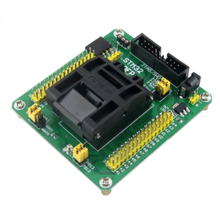
STM32 Programming Adapter Test Socket Conversion Module for LQFP64 Package 0.5mm Pitch
Features:
- 20-pin JTAG/SWD port and/or 4-pin USART1 interface for programming/testing
- External crystal can be connected via on board socket for system clock
- Onboard 32.768K crystal oscillator
- Two LED indicators for testing, which are connected to the I/O pins via jumpers
- All the MCU pins are accessible on expansion connectors
- Pin header pitch: 2.54mm(100mil)
Supported Devices:
STM32 microcontroller in QFP64(0.5mm pitch) package with compatible pinouts:
- STM32L1xxR series (STM32L151R8, STM32L152RB, etc.)
- STM32F0xxR series (STM32F051RC, STM32F051RB, etc.)
- STM32F1xxR series (STM32F103RC, STM32F100RB, etc.)
- STM32F2xxR series (STM32F207RC, STM32F215RB, etc.)
- STM32F3xxR series (STM32F303R8, STM32F373RB, etc.)
- STM32F4xxR series (STM32F407RC, STM32F415RB, etc.)
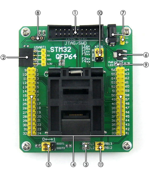
1. JTAG/SWD port
for programming/debugging/testing
compatible with ST-LINK / J-LINK / ULINK2 / STX-RLINK
2. USART1 port
supports ISP and/or serial port debugging
3. LED indicators
for quick testing
4. Pin headers connected to MCU pins
clearly labeled with onboard marks
easy for testing and further expansion
5. Boot mode configuration
configuring the BOOT0 and BOOT1 via jumpers
6. 3.3V onboard regulator
AMS1117-3.3
7. 5V power input
DC jack or 2-pin header
8. External crystal socket
insert crystal to the holes on two sides, leave alone the middle hole
9. Power indicator
10. Device selection jumpers
short the upper headers for STM32F1xx / STM32L1xx / STM32F05x / STM32F3xx
short the lower headers for STM32F2xx / STM32F4xx
11. LED jumpers
short the jumpers to connect LEDs to MCU I/O pins for testing
open the jumpers to disconnect
12. 32.768K crystal (on bottom side)
for internal RTC with calibration
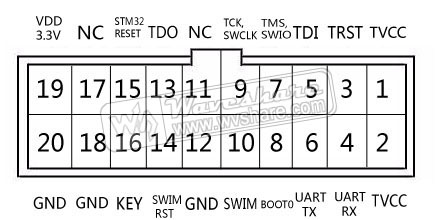
JTAG/SWD Connector Layout:
The STM32-QFP64 houses JTAG/SWD headers for connecting a programmer. The connector layout is shown in the figure 1 below.
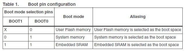
Boot Mode Configuration
Depending on the used pin configuration, the Flash memory, system memory or SRAM is selected as the boot space, as shown in Table 1 below.
Package Contains:
- STM32-QFP64 × 1
- USB power cable × 1