| Quantity | 3+ units | 10+ units | 30+ units | 50+ units | More |
|---|---|---|---|---|---|
| Price /Unit | $20.38 | $19.97 | $19.34 | $18.51 | Contact US |
 AXera PI Zero Module 5MP AI-ISP Camera Module Designed with SoC Chip AX620Q+SC450AI Image Sensor
$67.98
AXera PI Zero Module 5MP AI-ISP Camera Module Designed with SoC Chip AX620Q+SC450AI Image Sensor
$67.98
 0.5-inch 1024X768 OLED Driver Board High Quality Circuit Board for V760A-5 Wearable Head Mounted Display
$40.24
0.5-inch 1024X768 OLED Driver Board High Quality Circuit Board for V760A-5 Wearable Head Mounted Display
$40.24
 1PCS SFP+ Dual Mode Optical Module Small Form-factor Pluggable Transceiver Support 10Gbps Transmission with LC Interface
$26.09
1PCS SFP+ Dual Mode Optical Module Small Form-factor Pluggable Transceiver Support 10Gbps Transmission with LC Interface
$26.09
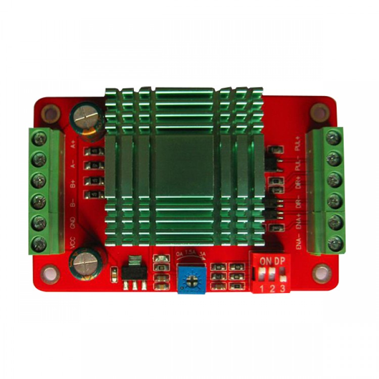
THB7128 Step Motor Drive Control Panel Current Subdivision Control Module
Description:
- SMDR01-THB7128Type sub-type two-phase hybrid stepping motor drives, DC91-32V power supply for the drive current0.5 -3.0A, outer diameter less than60Two-phase hybrid stepping motor mm,As39,42,57,60 stepper motors , etc.. This drive uses all-digital current loop subdivision control , small torque ripple of the motor, smooth running at low speed , low vibration and noise. When a relatively high -speed output torque , high positioning accuracy. Widely used in engraving machines, CNC machine tools, packaging machinery, transmission equipment and other requirements of the higher resolution devices .
Feature:
- Average current control, two -phase sinusoidal output current drive
- DC91-32V power supply
- High speedOptically isolated signal inputInterface
- Overvoltage, undervoltage , overcurrent, short circuit protection
- 8 file subdivision(1/2/4/8/16/32/64/128 )And automatic half current function
- Output phase current settingStepless adjustable 0.5-3A
- Start high speed,High-speed torque
- Has a power indicator light, set aside4A0.3mmBolt holes for easy installation ;
- Module size :5.0cm * 7.8cm * 1.6cm;
Instructions
- The figure is a schematic diagram of the function and organization of the stepper motor drives , we will combine the figure Intro proper use of stepper motor drives.
Current settings
- The maximum output current of the module3.3A( Peak ) , is rated3A; Could fit3AWithin the various2Small stepper motor phase current0.5 - 3AInfinitely adjustable to any setting. Module stepper motor phase current adjustment potentiometer is stepless , the current tick marks for reference.
- Note: The module requires a minimum drive current is set to0.5ASo, can not be set in0ALocation.
Set subdivision
- Total8 file subdivisionModes, namely 1/2/4/8/16/32/64/128 subdivided by three DIP switch settings on the module specific settings as shown below:
- Provided on the table,LOn behalf of the DIP switch toOFFPosition ,HOn behalf of the DIP switch toONLocation.
Signal input connection instructions
- PUL +: Positive pulse signal input terminal .
- PUL-: Negative pulse signal input terminal .
- DIR +: Stepping positive direction signal input terminal .
- DIR-: Stepping direction signal input negative terminal .
- ENA +: Offline enable reset signal positive terminal.
- ENA-: Offline enable reset signal negative terminal .
- Note:Offline enable reset two different signals with other signals , users can not connect , when that is no signal input , is to enable the driver to enter the working mode ; If a signal is input , the drive will go into sleep mode.
- PC control signal controller can be active high , you can also active low. When active high , all the negative terminal of the control signal as the signal ground together , when active low , all the positive terminal of the control signals together as a signal common terminal. Now with - - Open collector , for example, the interface circuit diagram is as follows :
- Input interface reference circuit2( Common cathode connection, active high )
- Note:VCCValue5VWhenRShort ;
- VCC Value12VWhenRAs1K ~ 1.2KGreater than1/8WResistance ;
- VCCValue24VWhenRAs2.7K ~ 3.3KGreater than1/8WResistance ;
- RMust be connected to the controller signals the end .
Motor winding connection
- A + Connect the motor windingsAPhase .
- A-: Connect the motor windingsA-Phase
- B +: Connect the motor windingsBPhase .
- B-: Connect the motor windingsB-Phase .
- Note: Do notAAndBPhase cross-connect , it will burn the drive. After debugging , best take a good electrical lines, measured with a multimeter drive terminals:A +,A-Is the same,B +,B-Are interlinked.A +AndB +Is not the same, so as to power on the test machine .
Power cable
- VCC: Connect the positive DC power supply voltage DC9~32VRecommended12Or24V.
- GND: Connect the DC power supply negative .
- Note: The drive power supply needed3AThe above output capacity , the power cord can not reverse .
Parameters:
- Input voltage : DC9V~32V
- Input Current:0.02A~3.0A
- Output Current:0A~3.0A
- Working temperature:-20~60
- Storage temperature:-40 ~80
- Humidity : not condensation, can not have water droplets
- Atmosphere : the prohibition of combustible gases and conductive dust
- Module weight :60Gram
Note:
- The drive power supply needed3AThe above output capacity , the power cord can not reverse .
- Stepper motor wiring may not beABPhase cross-connect , otherwise it will burn drive.
- Stepper motor drive signal in accordance with the default5VConfiguration level , if necessary3.3V,12VOr24VThe signal input configuration requires the prior statement ; or add their own current limiting resistor on the wiring,12VAdd1KLimiting resistor,24VAdd3KAbout limiting resistor.