| Quantity | 3+ units | 10+ units | 30+ units | 50+ units | More |
|---|---|---|---|---|---|
| Price /Unit | $16.77 | $16.43 | $15.91 | $15.23 | Contact US |
 0.5-inch 1024X768 OLED Driver Board High Quality Circuit Board for V760A-5 Wearable Head Mounted Display
$40.24
0.5-inch 1024X768 OLED Driver Board High Quality Circuit Board for V760A-5 Wearable Head Mounted Display
$40.24
 1PCS SFP+ Dual Mode Optical Module Small Form-factor Pluggable Transceiver Support 10Gbps Transmission with LC Interface
$26.09
1PCS SFP+ Dual Mode Optical Module Small Form-factor Pluggable Transceiver Support 10Gbps Transmission with LC Interface
$26.09
 1PCS Copper SFP Module Small Form-factor Pluggable Transceiver Support 10/100/1000M Transmission with RJ-45 Interface
$26.09
1PCS Copper SFP Module Small Form-factor Pluggable Transceiver Support 10/100/1000M Transmission with RJ-45 Interface
$26.09
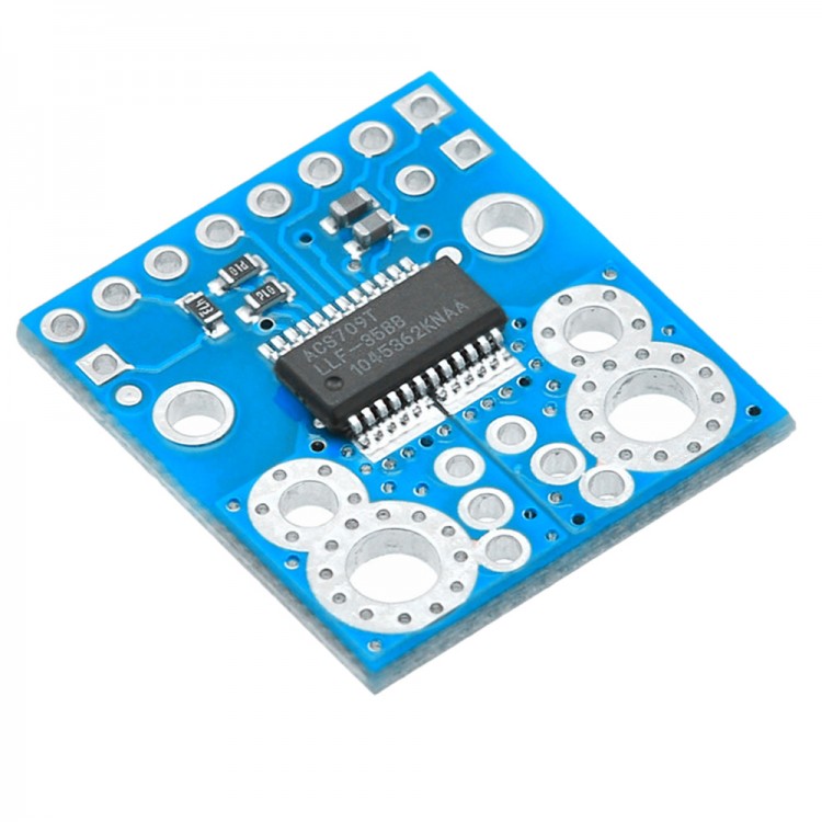
ACS709 Current Sensor -75A to 75A Module 120KHZ Bandwidth for Arduino DIY
Description:
The current sensor module is based on the Holzer effect of the linear current sensor which has a flow fault output; therefore, please read Datasheet ACS709. The sensor has the working voltage is 3 V to 5.5 V and when VCC is 3.3 V, 18.5 MV / A output sensitivity. When VCC = 5 V, 28 MV /A output sensitivity.
Features:
- The optimal accuracy of the bidirectional input current is from -37.5A to 37.5 A, with a linear detection range from A -75 to 75 A .
- The internal resistance of the conductive path is usually 1.1mOhm, and the PCB is made of 2 ounces of copper. Greatly reduce the capacitive coupling, to prevent offset drift in the high-end applications.
- Using the Holzer effect sensor device, the integrated circuit is capable of electrically isolating the current path from the sensor's electronic device (up to 2100 V RMS), which allows the sensor to be inserted in any place along the current path and in the need for electrical applications to be used in isolation.
- The bandwidth is 120 kHz can be selectively reduced by the addition of the "FILT" board of directors with a capacitor.
- High accuracy and reliability: 2% at room temperature with factory calibration, work temperature range from -40 to 150 deg C.
- The user can set the overcurrent threshold: the FAULT pin output remains low, when the current exceeds the threshold value of a time configuration can be set by an external capacitor.
Electrical connection:
The only required to use the sensor is in the input current (IP + and IP-), the logic power (VCC and GND), and the sensor output (VIOUT). All other pins are optional.
The sensor is required for 3 V to 5.5 V power supply voltage VCC and GND pad, which is labeled as the screen layer attached to the bottom of the screen. Sensor output analog voltage, which is proportional to the input current. Static output voltage is VCC/ 2 and each of the input current (when amperometric VCC=5V) of the change of the 28 MV, to the positive current increases output voltage and a negative current to decrease the output voltage. For an arbitrary input current I (the unit is an AMP), the output voltage of the sensor can be more generally expressed as:
VIOUT= (0.028 V / I * +2.5 V A) * V VCC/5
The VZCR is the reference voltage output pin, and can be used as a reference for zero current (0). This will be approximately equal to VCC/ 2, which can be more accurately calculated from the VIOUT output current.
The FILT pin allows you to adjust the board's bandwidth by adding a capacitor, CF, to the ground (ground mat has been added to the next FILT pin for convenience). Without any external filter capacitor, the bandwidth is 120000 hz. Data table provides more information on how the external filter capacitor affects the bandwidth.
The FAULT pin is typically high and low lock when the current exceeds the overcurrent fault switching point (IOC). This switching point is applied to the voltage on the VOC pin, and depends on the voltage regulator shown in the following diagram. By default, the Ioc is set to 57 A, but it can be changed by adding an external resistor divider to change the volatile organic compound. Once the fault pin is locked to a low level, it can be driven by the FAULT_EN input low level reset (the input is pulled high on the blackboard). An external capacitor, COC, can be added to enable the overcurrent fault response time. If there is no such capacitor, the fault response time is usually 2us. For detailed information on the use of a flow failure feature, including a number of key constraints on the overcurrent threshold, see the ACS709 data sheet
The screen printing is marked on the bottom, as shown in the image above. Silk screen printing also shows that the direction of the + I arrow is current flowing.
Note: the range of the extended A -75 to 75A of the sensor should be limited in the transient current. In our tests, we found that the IC can be tolerated at 50 A, 20 seconds or 150 a maximum of 37.5 seconds before the maximum temperature rating of 150. Therefore, unless you are taking special measures to keep the IC cool, we recommend limiting the continuous current of 30 A. even if the 1.1m is a low on resistance path, the chip can be enough to burn you when the current in tens of AMPS, and IC does not provide any type of ultra temperature protection, so the thermal problem should be considered for high current.
Package included:
- 1 x Current Sensor