| Quantity | 3+ units | 10+ units | 30+ units | 50+ units | More |
|---|---|---|---|---|---|
| Price /Unit | $15.50 | $15.19 | $14.71 | $14.08 | Contact US |
 Waveshare ESP32-S3 Development Board ESP32-S3R2 GEEK 1.14-inch LCD ST7789 for USB Dongle Support 2.4GHz WiFi BLE5
$17.68
Waveshare ESP32-S3 Development Board ESP32-S3R2 GEEK 1.14-inch LCD ST7789 for USB Dongle Support 2.4GHz WiFi BLE5
$17.68
 M5Stack M5GO IoT Starter Kit V2.7 High Performance IoT Start Development Kit ESP32 2-inch IPS Screen for Arduino
$96.24
M5Stack M5GO IoT Starter Kit V2.7 High Performance IoT Start Development Kit ESP32 2-inch IPS Screen for Arduino
$96.24
 M5Stack Glass2 Unit 1.51-inch Transparent OLED Extended Screen Unit for SSD1309 Driver Solution
$34.22
M5Stack Glass2 Unit 1.51-inch Transparent OLED Extended Screen Unit for SSD1309 Driver Solution
$34.22
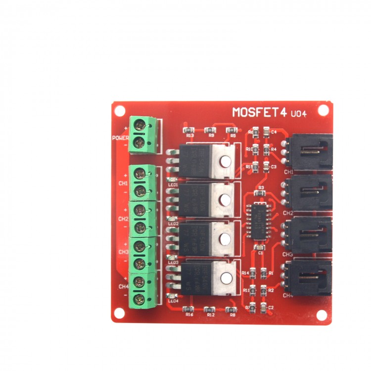
Arduino 4 Route MOSFET Button IRF540 V2.0+
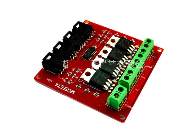
Product Description:
- MOSFET is an electronic devices with good switching characteristics. It is widely used in circuits, such as power supplies switching ,motor drives, lighting dimmer and so on.
- Relay is another kind of module with switching characteristics. Since relay works relying on mechanical contacts to open or shut. In this way it s will inevitably lead to relay's stopping working while switching time is too short. And papa sound made by relay in some situations is annoying.
- We designed a 4-channel MOSFET switch. It can supply up to four groups of electronic switches to control different circuit blocks respectively. Limited by the working priciples, MOSFET can only be used to control the DC circuit, such as DC-LED screen and so on, but not suitable for AC circuit control.
- In some extreme cases,It can be used to control 100V/33A DC circuit. However, it is suggested that the controlled DC voltage is more than 9V.
Connection Procedure:
- The connection for the control tip is a little trouble in the circuit connection.For example, the lamp belt
controlling 12V LED, first you should connect the power supply between the positive (+) and negative (-).
- Then connect the the LED light belt positive (+) to the module positive (+).Connect the LED lamp belt negative (-) to the switch 1(S1).
- If there are other LED light need to control, you only need to connect the LED lamp belt to the module positive (+).Mainwhile,the LED lamp belt negative (-) connects to the switch 2(S2) and switch 3 (S3), switch 4 (S4) in turns.
- The control side connection is much simpler. We only need to connect corresponding control port to the Arduino sensor expansion plate through the sensor conjunction wire.We can control these 12V LED lamp belt through Arduino.
We take two LED lights in the experiment.
The test code is as follows:
int s1Pin = 6; int s2Pin = 7; void setup() { pinMode(s1Pin, OUTPUT); pinMode(s2Pin, OUTPUT); } void loop() { int i; digitalWrite(s1Pin, HIGH); digitalWrite(s2Pin, HIGH); delay(500); digitalWrite(s1Pin, LOW); digitalWrite(s2Pin, LOW); delay(500); for (i = 0; i < 10; i ++) { digitalWrite(s1Pin, HIGH); delay(500); digitalWrite(s1Pin, LOW); delay(500); } for (i = 0; i < 100; i ++) { digitalWrite(s2Pin, HIGH); delay(50); digitalWrite(s2Pin, LOW); delay(50); } }

User video:Click here
Package List:
- 1 x Arduino 4 Route MOSFET Button IRF540 V2.0+


")
")


