| Quantity | 3+ units | 10+ units | 30+ units | 50+ units | More |
|---|---|---|---|---|---|
| Price /Unit | $46.98 | $46.02 | $44.58 | $42.67 | Contact US |
 Black 3D-Printed Mini ESP32 Marauder Development Board Positioning Module with 1.44-inch Screen
$33.36
Black 3D-Printed Mini ESP32 Marauder Development Board Positioning Module with 1.44-inch Screen
$33.36
 White 3D-Printed Mini ESP32 Marauder Development Board Positioning Module with 1.44-inch Screen
$33.36
White 3D-Printed Mini ESP32 Marauder Development Board Positioning Module with 1.44-inch Screen
$33.36
 MPSoC XCZU19EG-F V0.3 AMR+FPGA Development Board Kit QSFP28 10Gbps Ethernet PCIE3.0 Support for Windows/Linux Systems
$1,537.98
MPSoC XCZU19EG-F V0.3 AMR+FPGA Development Board Kit QSFP28 10Gbps Ethernet PCIE3.0 Support for Windows/Linux Systems
$1,537.98
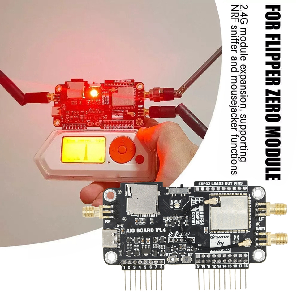
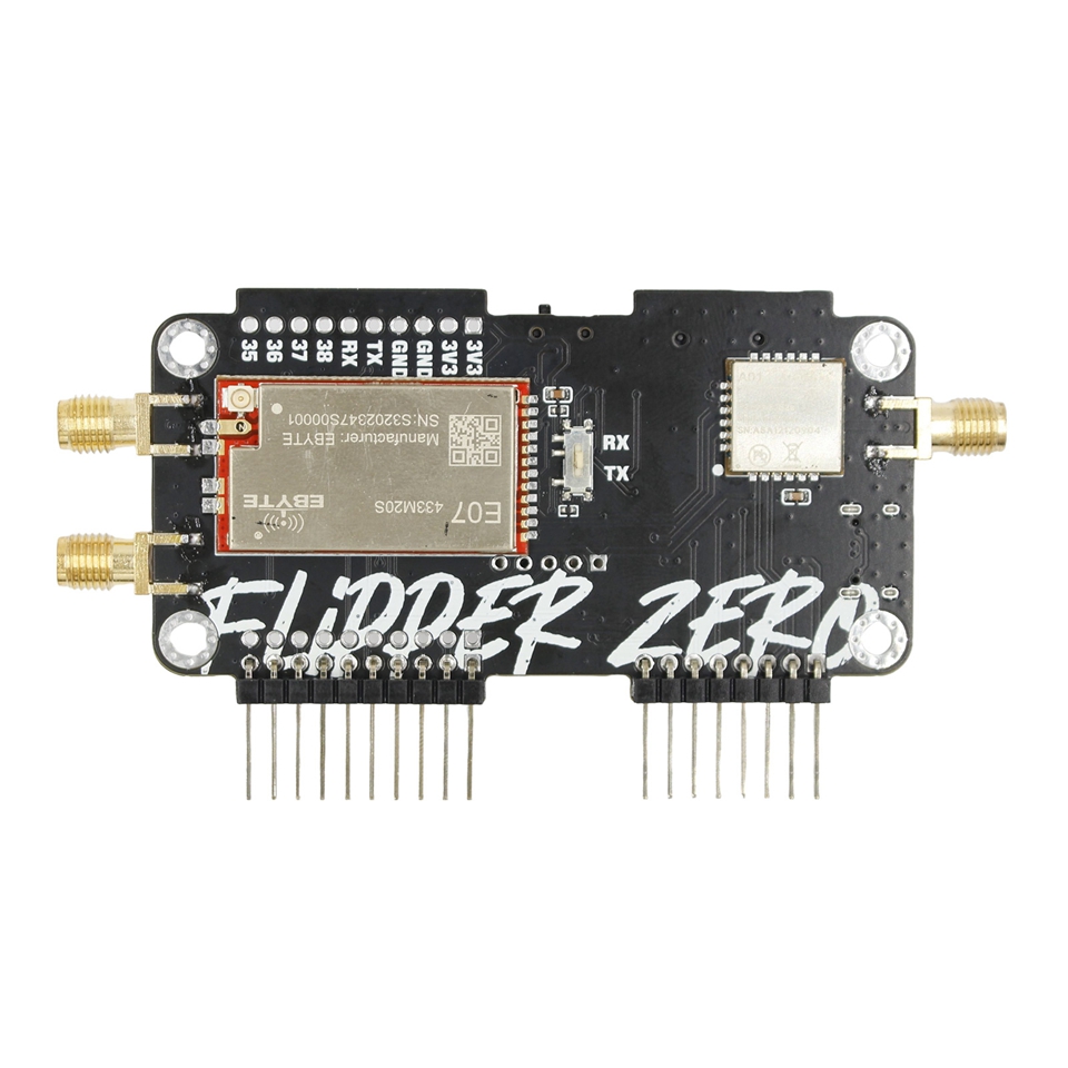
NRF24+ESP32 Multifunctional Expansion Module WiFi 3-IN-1 Modification Module for Flipper Zero
Functions:
- WiFi function expansion, flash ESP32Marauder firmware by default, support SD card storage data.
- 2.4G module expansion, supporting for NRF sniffer and mousejacker functions.
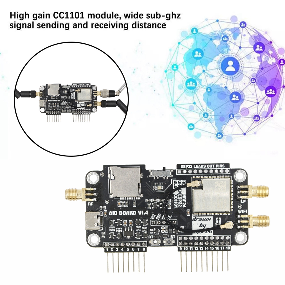
- High gain CC1101 module, wide sub-ghz signal sending and receiving distance.
- Applicable models: for Flipper zero
Package Included:
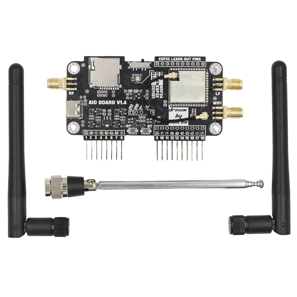
- 1 x Expansion Module
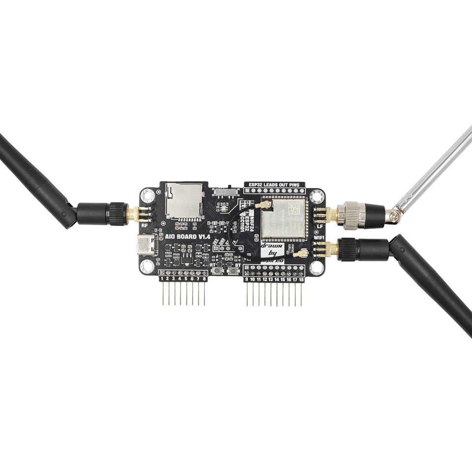
- 1 x 2.4/5GHz Antenna
- 1 x 40MHz - 6GHz Wideband Telescopic Antenna
Using Instruction:
Function Switch:
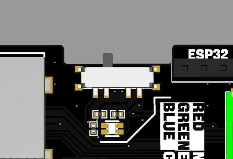
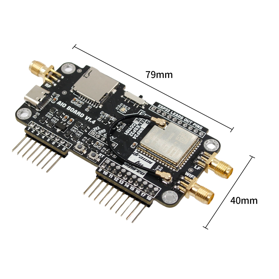
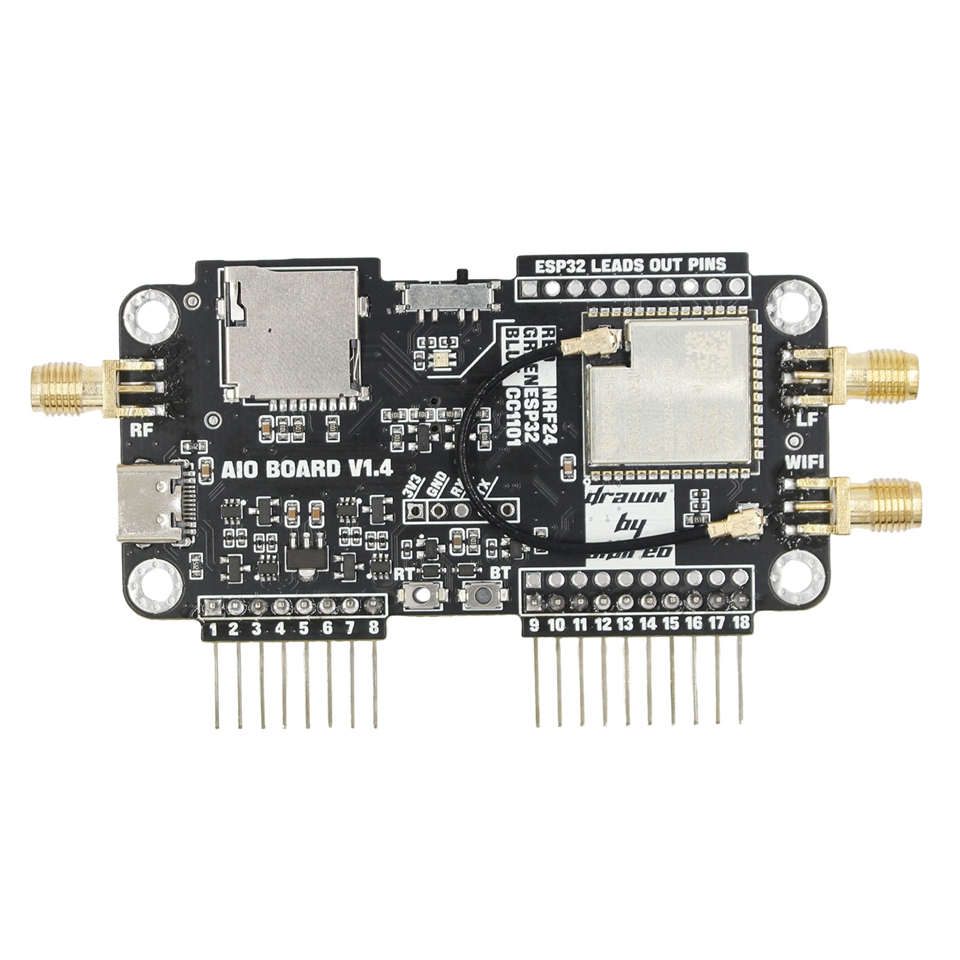
- There is a function switch button on the top of the PCB, which can be switched among the three module functions by toggling the switch. The LED below the switch is used to indicate the current function: the red light indicates that it is a 2.4GHz transceiver module, the green light indicates that it is a WIFI module, and the blue light indicates that it is a CC1101 module.
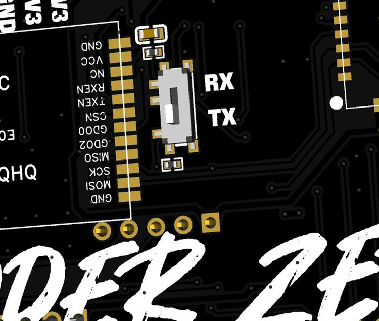
- The switch on the back of the PCB is used to turn on the built-in gain circuit of the CC1101 module. When the switch is in RX mode, the receiving function of the CC1101 module gains, and when the switch is in TX mode, the transmitting function of the module gains. When the switch is in the RX position, the module can also perform receiving function, but the TX function does not have gain amplification.
- Note: Do not directly plug or unplug the module when it is powered on, as it may damage the module's power supply function.
ESP32 Program Writing:
- The WIFI module selected on the PCB is ESP32-S2. When downloading the program, you can refer to the writing process of the official WIFI board for Flipper Zero.
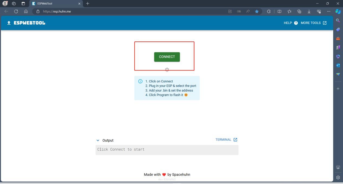
1. Open the following website through a browser: ESPWebTool (huhn. me) (using Edge browser)
2. Turn the toggle switch above the front of the PCB board to the middle position.
3. Press and hold the boot button below the front of the PCB (the silk screen next to the button is BT), and connect the TYPE-C interface on the PCB to the computer interface through a USB cable. At this time, the LED color on the front of the PCB should be green.
4. Click the CONNECT button on the webpage.
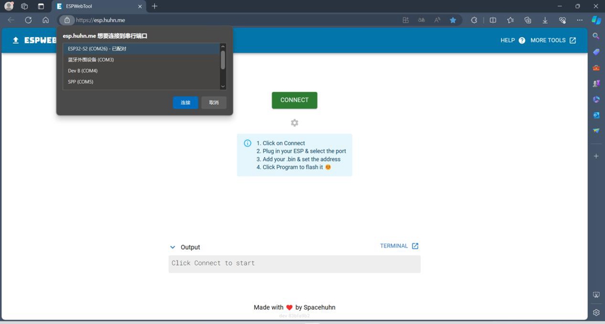
5. Select the ESP32-S2 chip in the upper left corner prompt window.
6. Add the downloaded file to the corresponding address as shown in the diagram.
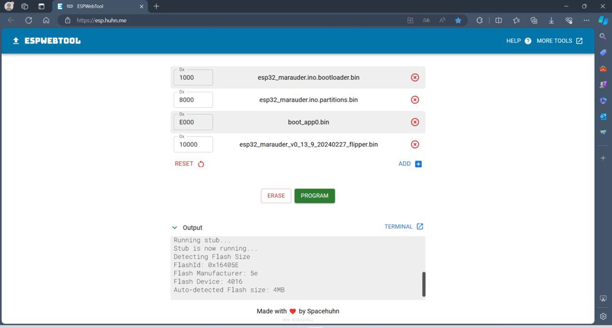
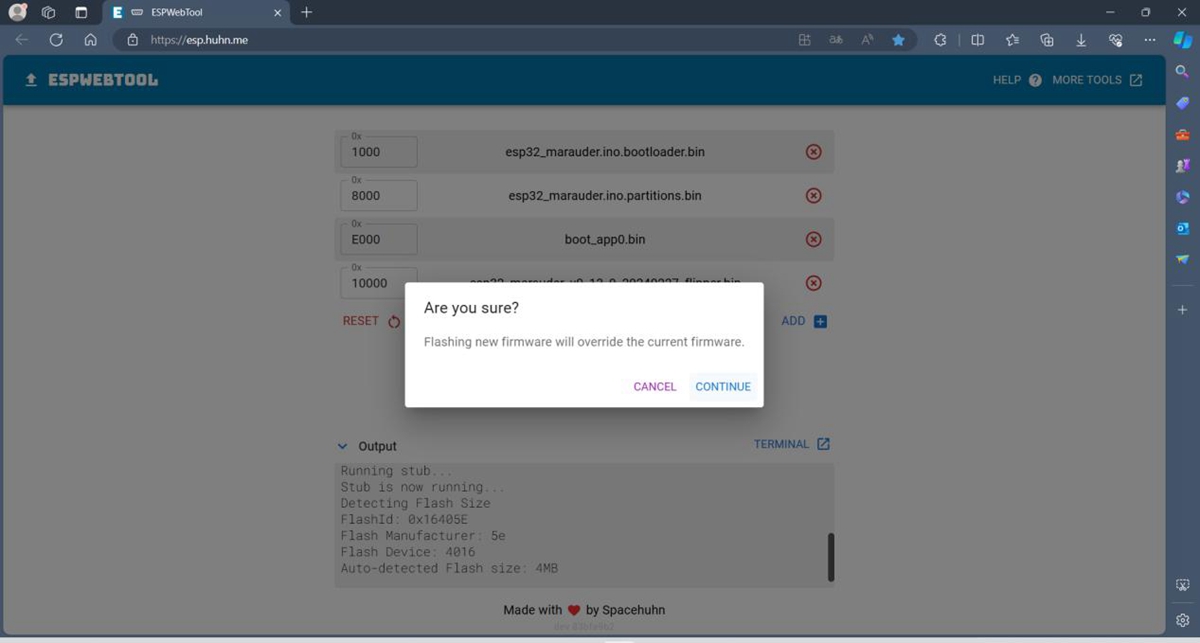
7. Click the PROGRAM button to start downloading, a window will pop up after clicking, and click CONTINUE to continue.
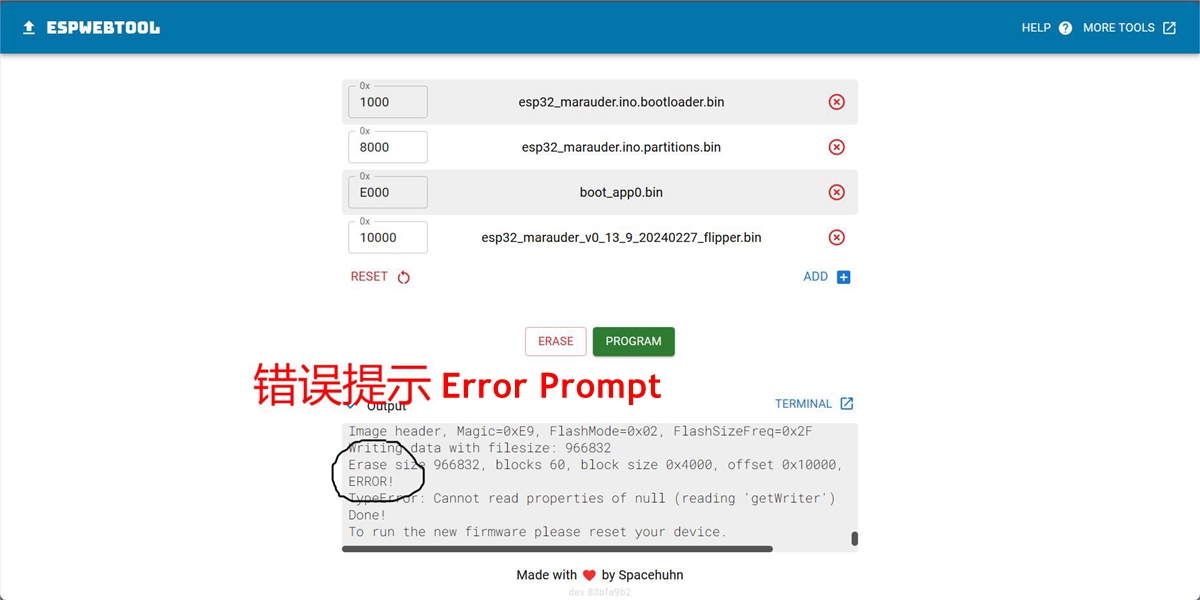
8. After the download progress reaches 100%, it will prompt that the download is completed. If the download progress is interrupted halfway, it will prompt an ERROR message. Then, check whether the module soldering and USB interface are securely connected to the computer. After checking, reconnect to the computer for writing.
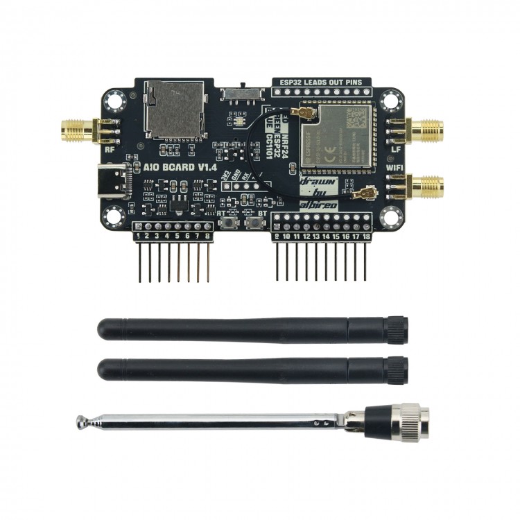


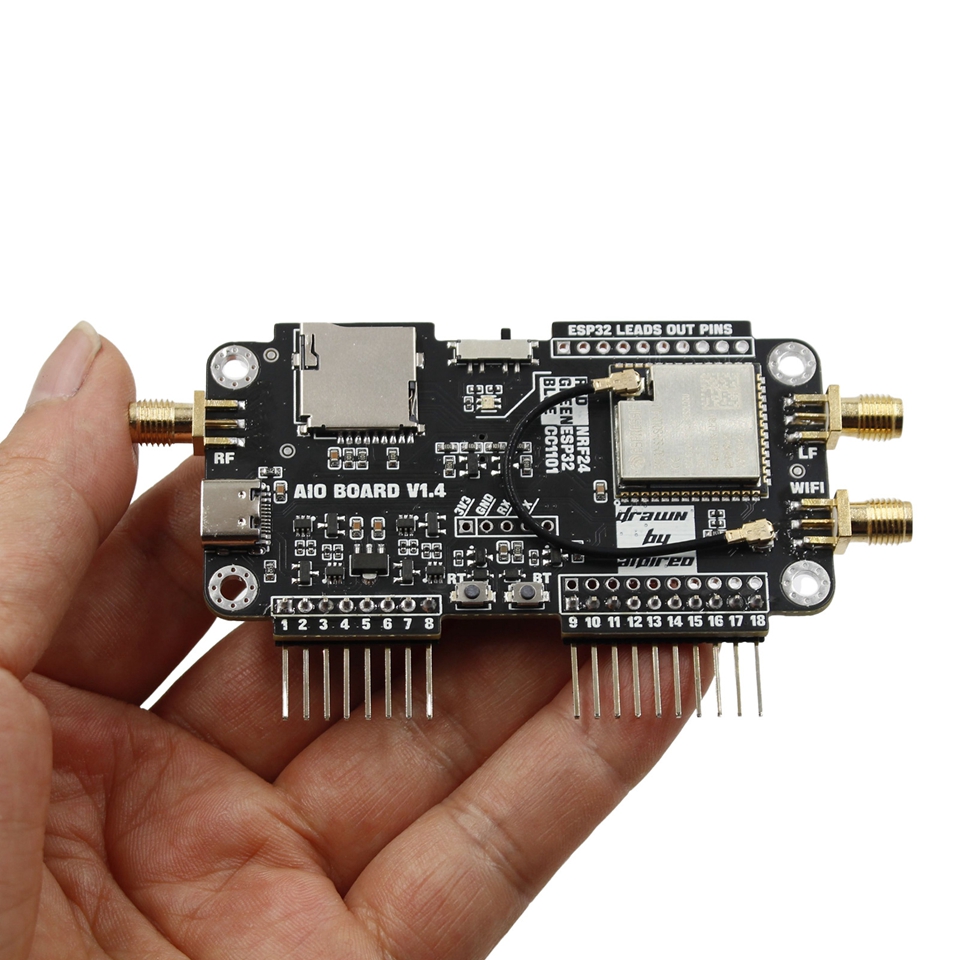
 Integrated Backpacks Expansion Module Opensource RF Development Board for Flipper Zero")


")

