| Quantity | 3+ units | 10+ units | 30+ units | 50+ units | More |
|---|---|---|---|---|---|
| Price /Unit | $32.50 | $31.83 | $30.84 | $29.51 | Contact US |
 Line Magnetic Audio LM-508IA 48W+48W Tube Amplifier Integrated Amplifier Tube Amp with Two VU Meters
$2,624.45
Line Magnetic Audio LM-508IA 48W+48W Tube Amplifier Integrated Amplifier Tube Amp with Two VU Meters
$2,624.45
 2x80W HiFi Digital Power Amplifier Board V1.6 Class D Amplifier Board for MERUS MA12070 with Toggle Switch
$33.44
2x80W HiFi Digital Power Amplifier Board V1.6 Class D Amplifier Board for MERUS MA12070 with Toggle Switch
$33.44
 Rod Rain Audio TPA3116 2.0 100Wx2 Class D Amp BT5.3 Digital Power Amplifier Power Amp (Black)
$34.82
Rod Rain Audio TPA3116 2.0 100Wx2 Class D Amp BT5.3 Digital Power Amplifier Power Amp (Black)
$34.82
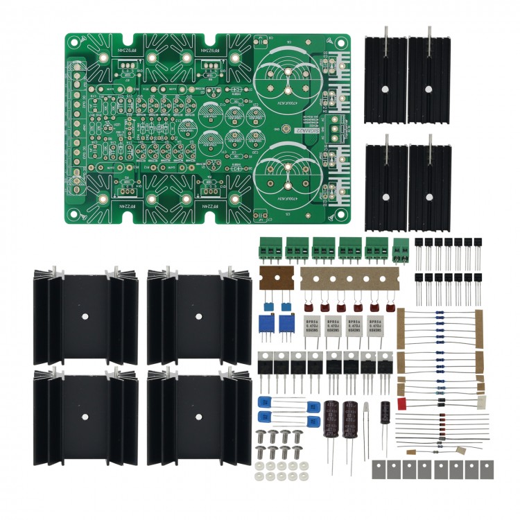
SIGMA22 Green Board Power Supply Kit Adjustable Voltage Regulator For DAC Headphone Amplifier
Comparison of Blue Board and Green Board:
The blue board is a layout close to the original board. The green board is suitable for higher current because of the four rectifier diodes that can be added to the radiator. In addition, the adjustment tubes of these two boards can be installed horizontally on the bottom of the chassis to dissipate heat.
Description:
The kit includes PCB board, heat sink, resistors and capacitors, but does not include main filter capacitors.
Attention:
Since 5th February, 2021, the 100UF and 470UF capacitors in the kit have been replaced with KZE series (brown ones). The ESR of the KZE series is lower than that of the LXZ series.
1.This SIGMA22 kit is only suitable for users with a certain electronic knowledge and soldering iron soldering ability.
2.Due to the different purchase batches, some components will be replaced without notice under the premise of ensuring quality.
3. This kit does not include a chassis, power transformer, or main filter capacitors.
4. SIGMA22 PCB board parameters, blue board size 150x90MM/5.9x3.5", green board 150x100MM/5.9x3.9", both are 1.6mm/0.06", 2 OZ.
5. When R10 is 10K, the output voltage is 23~24V (also the default output voltage of this kit), and there is an extra 50K 3296 adjustment.
6. The AC voltage supplying the board should not exceed AC35V.
7. For other output voltages, a rule of thumb is that under load, a voltage drop of about 9V-10V should be maintained through the mosfet.
8. This kit contains the insulation sheet (or not for insulation) and insulation particles used for the power adjustment tube, and is equipped with 8 stainless steel screws.
9. If the rectifier diode and adjustment tube are installed in a chassis and the bottom shell of the chassis is used as a radiator, they must all be insulated, otherwise the tubes will burn!
10. For the convenience of users, a 5V and 12V voltage regulator tube are equipped.
The relationship between R10 and the output voltage value is as follows:
Output Voltage R10 Value Zener Diode (D5)
±36V 4.99K BZX55C12 (12V)
±30V 6.81K BZX55C12 (12V)
±27V 7.87K BZX55C12 (12V)
±24V 10K BZX55C12 (12V)
±15V 39.2K BZX55C12 (12V)
±12V not installed BZX55C12 (12V)
±9V not installed BZX55C9V1 (9.1V)
±5V not installed BZX55C5V1 (5.1V) or LM336-5.0 (ADJ pin unused)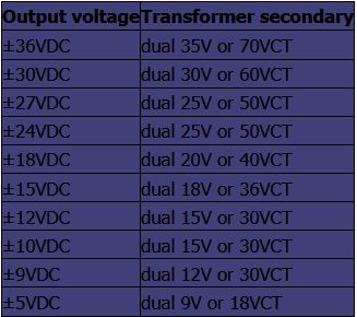
Package Included:
- 1 x Set of Power Supply
Note:
- It is unassembled and assembling is needed.