| Quantity | 3+ units | 10+ units | 30+ units | 50+ units | More |
|---|---|---|---|---|---|
| Price /Unit | $68.32 | $66.92 | $64.83 | $62.04 | Contact US |
 AXera PI Zero Module 5MP AI-ISP Camera Module Designed with SoC Chip AX620Q+SC450AI Image Sensor
$67.98
AXera PI Zero Module 5MP AI-ISP Camera Module Designed with SoC Chip AX620Q+SC450AI Image Sensor
$67.98
 0.5-inch 1024X768 OLED Driver Board High Quality Circuit Board for V760A-5 Wearable Head Mounted Display
$40.24
0.5-inch 1024X768 OLED Driver Board High Quality Circuit Board for V760A-5 Wearable Head Mounted Display
$40.24
 1PCS SFP+ Dual Mode Optical Module Small Form-factor Pluggable Transceiver Support 10Gbps Transmission with LC Interface
$26.09
1PCS SFP+ Dual Mode Optical Module Small Form-factor Pluggable Transceiver Support 10Gbps Transmission with LC Interface
$26.09
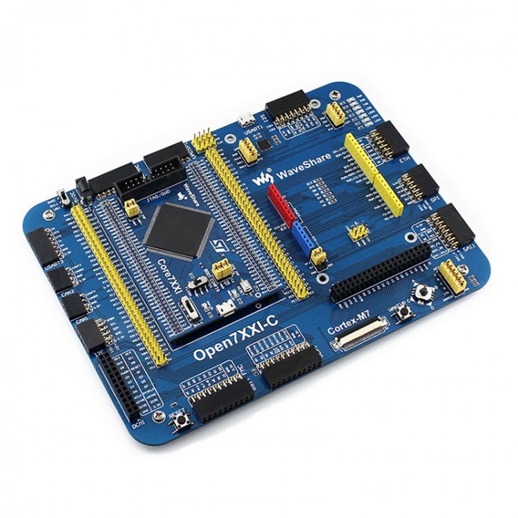
STM32F746IGT6 ARM Cortex-M7 Development Board + Power Supply for Arduino
User manual: Click here
Core746I Schematic diagram : Click here
Open746I-C Schematic diagram : Click here
More information: Click here
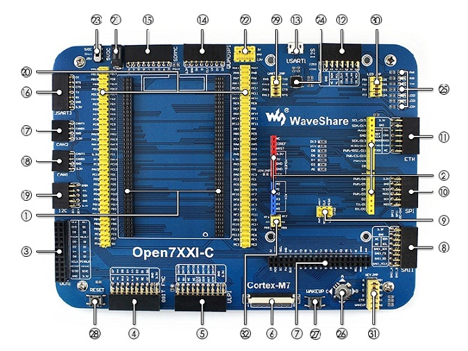
1. MCU core board connector: for easily connecting the Core746I
2. Arduino interface: for connecting Arduino shields
3. DCMI interface: for connecting camera
4. 8-bit FMC interface: easily connects to peripherals such as NandFlash
5.ULPI interface: for connecting high-speed USB peripheral (the STM32F746I integrates USB HS controller without any PHY device)
6. LCD interface 1: for connecting 10.1inch LCD, 7inch LCD
7. LCD interface 2: for connecting 4.3inch LCD
8. SAI1 interface: for connecting audio modules like UDA1380 module
9. ICSP interface: Arduino ICSP
10. SPI1/SPI2 interfaces:
easily connects to SPI peripherals such as DataFlash (AT45DBxx, W25QXX), SD card, MP3 module, etc.
easily connects to AD/DA modules (SPI1 features AD/DA alternative function)
11. Ethernet interface: for connecting Ethernet modules
12. I2S2/I2S3/I2C1 interface: easily connects to I2S peripherals such as audio module, etc.
13. USART1 connector: USB to UASRT via the onboard convertor CP2102
14. QUADSPI interface: 4-wires SPI interface (the F7 series latest peripheral interface), for connecting serial Flash modules like W25QXX Board
15. SDMMC interface: for connecting Micro SD module, features much faster access speed rather than SPI
16. USART3 interface: easily connects to RS232, RS485, USB TO 232, etc.
17. CAN2 interface: for connecting CAN modules
18. CAN1 interface: for connecting CAN modules
19. I2C1/I2C4 interface: easily connects to I2C peripherals such as I/O expander (PCF8574), EEPROM (AT24Cxx), 10 DOF IMU Sensor, etc.
20. MCU pins connector: all the MCU I/O ports are accessible on expansion connectors for further expansion
21. 5V DC jack
22. 5V/3.3V power input/output: usually used as power output, also common-grounding with other user board
23. Power supply switch: powered from 5VDC OR USB connection of the USART1
24. CP2102: USB to UART convertor
25. LEDs: convenient for indicating I/O status and/or program running state
26. Joystick: five positions
27. WAKE UP button: used as regular button, and/or wake up the STM32 MCU from sleep
28. Reset button
29. USART1 jumper
30. LED jumper
short the jumper to connect to default I/Os used in example code
open the jumper to connect to custom I/Os via jumper wires
31. KEY jumper
short the jumper to connect to default I/Os used in example code
open the jumper to connect to custom I/Os via jumper wires
32. Arduino jumper
short the upper pins, A4, A5 is used as AD function
short the lower pins, A4, A5 is used as I2C function
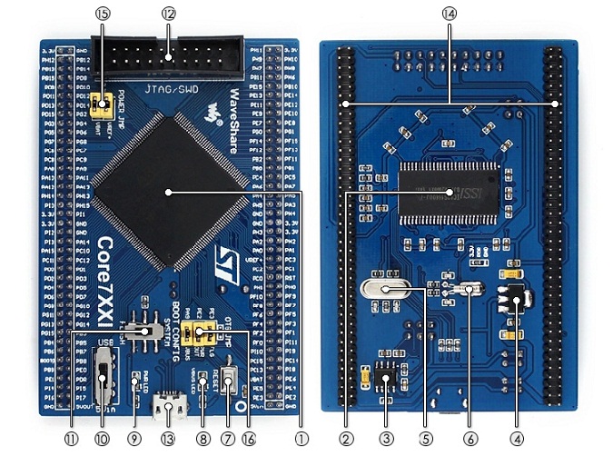
1. STM32F746IGT6: the high performance STM32 MCU which features:
- Core: Cortex-M7 32-bit RISC + FPU + Chrom-ART graphic accelerator
- Feature: single-cycle DSP instructions
- Operating Frequency: 216MHz, 462 DMIPS/2.14 DMIPS/MHz
- Operating Voltage: 1.7V-3.6V
- Package: LQFP176
- Memories: 1024kB Flash, 320+16+4kB SRAM
- MCU communication Interfaces:
6 x SPI, 4 x USART, 4 x UART, 3 x I2S, 4 x I2C
2 x CAN, 1 x QUAD-SPI, 1 x DCMI, 2 x SAI
1 x FMC, 1 x SDMMC, 14 x TIM , 1xLPTIM
1 xLCD-TFT, 1xSPDIFRX, 1xHDMI-CEC
1 x USB 2.0 OTG FS
1 x USB 2.0 OTG HS (supports external HS PHY through ULPI)
1 x 10/100 Ethernet MAC
- AD & DA converters: 3 x AD (12-bit); 2 x DA (12-bit)
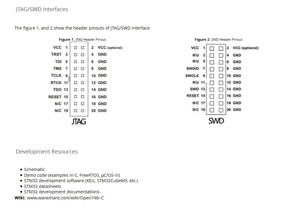
- Debugging/Programming: supports JTAG/SWD interfaces, supports IAP
2. IS42S16400J: SDRAM 1 Meg Bits x 16 Bits x 4 Banks (64-MBIT)
3. MIC2075: onboard USB power management device
4. AMS1117-3.3: 3.3V voltage regulator
5. 8M crystal
6. 32.768K crystal, for internal RTC with calibration
7. Reset button
8. VBUS LED
9. Power indicator
10. Power supply switch, powered from 5Vin or USB connection
11. Boot mode selection, for configuring BOOT0 pin
12. JTAG/SWD interface: for debugging/programming
13. USB connector, supports Device and/or Host
14. MCU pins expander, VCC, GND and all the I/O pins are accessible on expansion connectors for further expansion
15. Power jumper
VBAT: short the jumper to use system power supply, open it to connect external power, such as battery
VREF: short the jumper to connect VREF+ to VCC, open it to connect VREF+ to other custom pin via jumper wire
16. OTG jumper
short the jumper when using USB OTG/HOST
open the jumper to disconnect from related I/O port
PACKAGE CONTENT
- Open746I-C development board x 1
- USB type A plug to micro B plug cable x 1
- USB type A receptacle to micro B plug cable x 1
- 4-pin + 2-pin wires pack x 1
- 5V power adapter x 1
- User Guide CD x 1