| Quantity | 3+ units | 10+ units | 30+ units | 50+ units | More |
|---|---|---|---|---|---|
| Price /Unit | $7.49 | $7.33 | $7.11 | $6.80 | Contact US |
 0-10V/0-25mA 4-Channel Current Voltage Signal Generator Brightness Adjustable LED Signal Collector with 35MM DIN-Rail Base
$20.52
0-10V/0-25mA 4-Channel Current Voltage Signal Generator Brightness Adjustable LED Signal Collector with 35MM DIN-Rail Base
$20.52
 0-10V/0-25mA 4-Channel Current Voltage Signal Generator Module Brightness Adjustable LED Signal Collector
$18.57
0-10V/0-25mA 4-Channel Current Voltage Signal Generator Module Brightness Adjustable LED Signal Collector
$18.57
 Automobile Crank Shaft Synchronization Signal Simulator Module 6-Channel Output Signal Generator Module with LED Display
$64.45
Automobile Crank Shaft Synchronization Signal Simulator Module 6-Channel Output Signal Generator Module with LED Display
$64.45
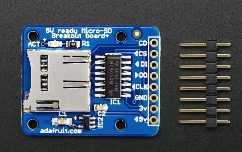
Product Description:
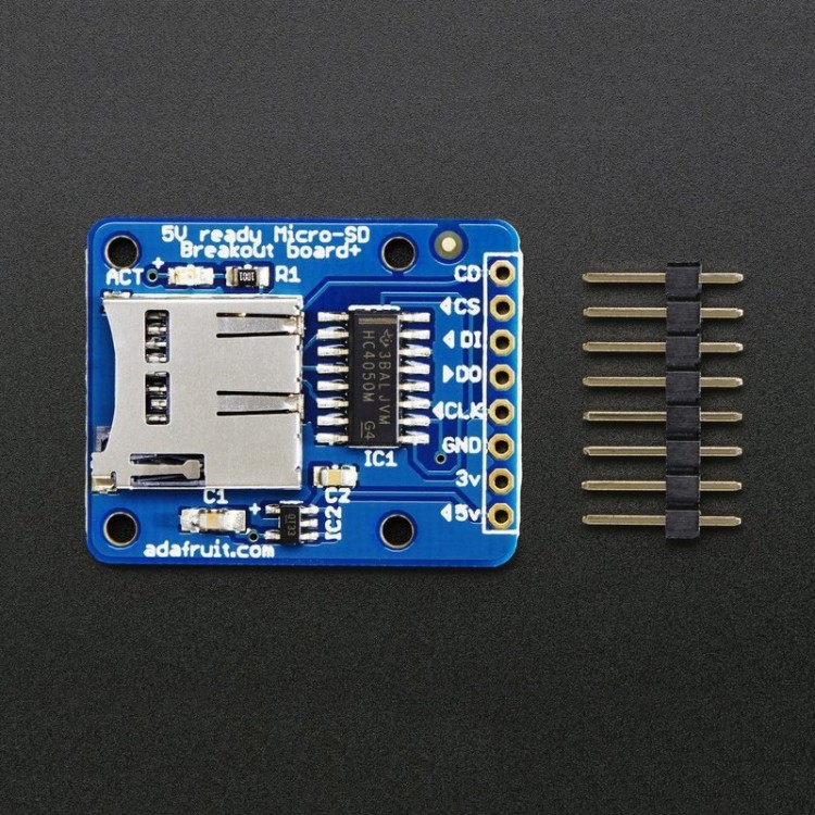
- To use with an Arduino, connect GND to ground, 5V to 5V, CLK to pin 13, DO to pin 12, DI to pin 11, and CS to pin 10. Then you can use the Arduino IDE's SD library which supports FAT and FAT32 SD cards
- If you have a project with any audio, video, graphics, data logging, etc in it, you'll find that having a removable storage option is essential. Most microcontrollers have extremely limited built-in storage. For example, even the Arduino Mega chip (the Atmega2560) has a mere 4Kbytes of EEPROM storage. There's more flash (256K) but you can't write to it as easily and you have to be careful if you want to store information in flash that you don't overwrite the program itself!
- If you're doing any sort of data logging, graphics or audio, you'll need at least a megabyte of storage, and 64 M is probably the minimum. To get that kind of storage we're going to use the same type that's in every digital camera and mp3 player: flash cards! Often called SD or microSD cards, they can pack gigabytes into a space smaller than a coin. They're also available in every electronics shop so you can easily get more and best of all, many computers have SD or microSD card readers built in so you can move data back and forth between say your Arduino GPS data logger and your computer graphing software.
Specification:
- Onboard 5v->3v regulator provides 150mA for power-hungry cards
- 3v level shifting means you can use this with ease on either 3v or 5v systems
- Uses a proper level shifting chip, not resistors: less problems, and faster read/write access
- Use 3 or 4 digital pins to read and write 2Gb+ of storage!
- Activity LED lights up when the SD card is being read or written
- Four #2 mounting holes
- Push-push socket with card slightly over the edge of the PCB so its easy to insert and remove
- Comes with 0.1" header (unattached) so you can get it on a breadboard or use wires - your choice
- Tested and assembled here at the Adafruit factory
- Works great with Arduino, with tons of example code and wiring diagrams
There are a few things to watch for when interacting with SD cards:
- One is that they are strictly 3.3V devices and the power draw when writing to the card can be fairly high, up to 100mA (or more)! That means that you must have a fairly good 3.3V power supply for the card. Secondly you must also have 3.3V logic to interface to the pins. We've found that SD cards are fairly sensitive about the interface pins - the newest cards are edge triggered and require very 'square' transitions - things like resistor dividers and long wires will have a deleterious effect on the transition speed, so keep wires short, and avoid using resistor dividers for the 3.3V logic lines. We suggest instead using level shifters, such as HEF4050, 74LVX245 or 74AHC125 chips.
- Secondly, there are two ways to interface with SD cards - SPI mode and SDIO mode. SDIO mode is faster, but is more complex and as far as we can tell, requires signing non-disclosure documents. For that reason, you will likely never encounter SDIO mode interface code. Instead, every SD card has a 'lower speed' SPI mode that is easy for any microcontroller to use. SPI mode requires four pins (we'll discuss them in detail later) so it's not pin-heavy like some parallel-interface components
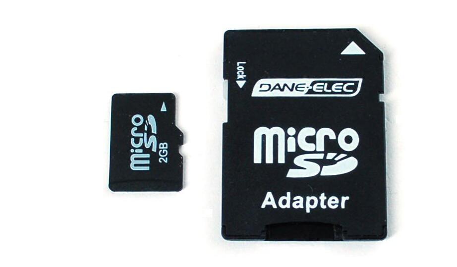
SD cards come in two popular flavors - microSD and SD. The interface, code, structure, etc is all the same. The only differences is the size. MicroSD are much much smaller in physical size.
- Third, SD cards are 'raw' storage. They're just sectors in a flash chip, there's no structure that you have to use. That means you could format an SD card to be a Linux filesystem, a FAT (DOS) filesystem or a Mac filesystem. You could also not have any filesystem at all! However, 99% of computers, cameras, MP3 players, GPS loggers, etc require FAT16 or FAT32 for the filesystem. The tradeoff here is that for smaller microcontrollers (like the Arduino) the addition of the complex file format handling can take a lot of flash storage and RAM.
Formatting notes:
Even though you can/could use your SD card 'raw' - it's most convenient to format the card to a filesystem. For the Arduino library we'll be discussing, and nearly every other SD library, the card must be formatted FAT16 or FAT32. Some only allow one or the other. The Arduino SD library can use either.
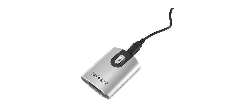
If you bought an SD card, chances are it's already pre-formatted with a FAT filesystem. However you may have problems with how the factory formats the card, or if it's an old card it needs to be reformatted. The Arduino SD library we use supports both FAT16 and FAT32 filesystems. If you have a very small SD card, say 8-32 Megabytes you might find it is formatted FAT12 which isn't supported. You'll have to reformat these card. Either way, it's always good idea to format the card before using, even if it's new! Note that formatting will erase the card so save anything you want first.
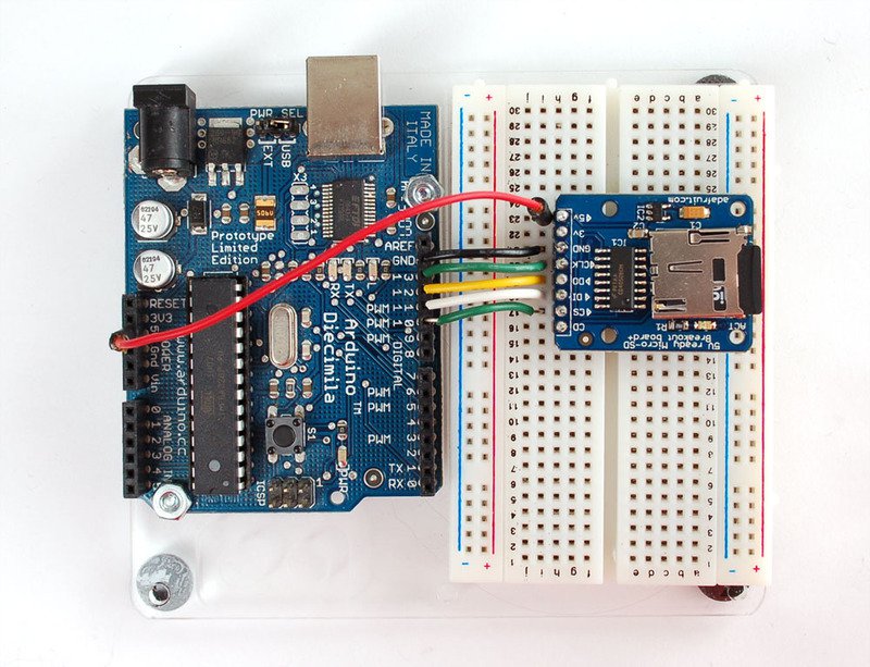
Wiring:
Now that your card is ready to use, we can wire up the microSD breakout board! The breakout board we designed takes care of a lot for you. There's an onboard ultra-low dropout regulator that will convert voltages from 3.3V-6v down to ~3.3V (IC2). There's also a level shifter that will convert the interface logic from 3.3V-5V to 3.3V. That means you can use this board to interact with a 3.3V or 5V microcontrollers.
In this tutorial we will be using an Arduino to demonstrate the wiring and interfacing. If you have another microcontroller, you'll need to adapt the wiring and code to match!
Because SD cards require a lot of data transfer, they will give the best performance when connected up to the hardware SPI pins on a microcontroller. The hardware SPI pins are much faster than 'bit-banging' the interface code using another set of pins. For 'classic' Arduinos such as the Duemilanove/Diecimila/Uno those pins are digital 13 (SCK), 12 (MISO) and 11 (MOSI). You will also need a fourth pin for the 'chip/slave select' (SS) line. Traditionally this is pin 10 but you can actually use any pin you like. If you have a Mega, the pins are different! You'll want to use digital 50 (MISO), 51 (MOSI), 52 (SCK), and for the CS line, the most common pin is 53 (SS). Again, you can change the SS (pin 10 or 53) later but for now, stick with those pins.
Connect the 5V pin to the 5V pin on the Arduino
Connect the GND pin to the GND pin on the Arduino
Connect CLK to pin 13 or 52
Connect DO to pin 12 or 50
Connect DI to pin 11 or 51
Connect CS to pin 10 or 53
There's one more pin CD - this is the Card Detect pin. It shorts to ground when a card is inserted. You should connect a pull up resistor (10K or so) and wire this to another pin if you want to detect when a card is inserted. We won't be using it for now.
Package List:
- 1 x MicroSD Card module
- 1 x Schematic diagram
- 1 x Chip datasheet


 Programmable Watch ESP32 Watch Development Board")
")


