| Quantity | 3+ units | 10+ units | 30+ units | 50+ units | More |
|---|---|---|---|---|---|
| Price /Unit | $17.79 | $17.42 | $16.88 | $16.15 | Contact US |
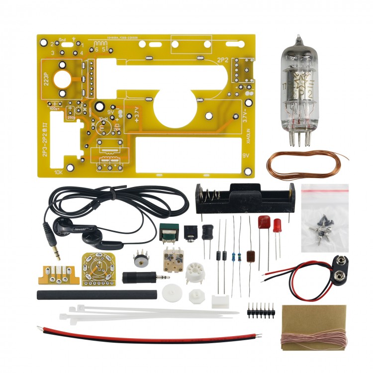
2P2 Tube Single Light MW Radio Kit Simple Radio Receiver Kit (without Shell) for DIY
Attention:
- Magnetic rod coil need to be wound by yourself! With cotton-covered wire and varnished wire.
- It fits 2P3 shell which is not included and can be purchased separately. Battery and loudspeaker (cannot be driven) are not included.
- The radio should be connected to antenna and small amplifier speakers, otherwise its sound will be too low to be heard.
- Small amp speakers such as cellphone Bluetooth speakers with input cable and small small computer speakers. And they should be connected for the first debugging!
- It can only receive 1-2 local radio stations with strong signals, so the kit is only suitable for enthusiasts to DIY.
Radio Kit Description:
Its potentiometer have the function of switching and regenerative adjustment.
14500 lithium battery DC 3.7V and 9V power supply and screen voltage 9V. The screen current is less than 0.5mA.
Filament 2.4V power supply: Pin 7 (positive pole), pin 1 (negative pole), and pin 5 (empty). The filament current is 30mA .
The lamp base with red LED powered by 2.4V and current limiting resistance 150Ω. LED current 16mA.
After transformer impedance conversion, it can support 8-32Ω headphones. When not connected to a transformer, it can use 2000-4000Ω headphones.
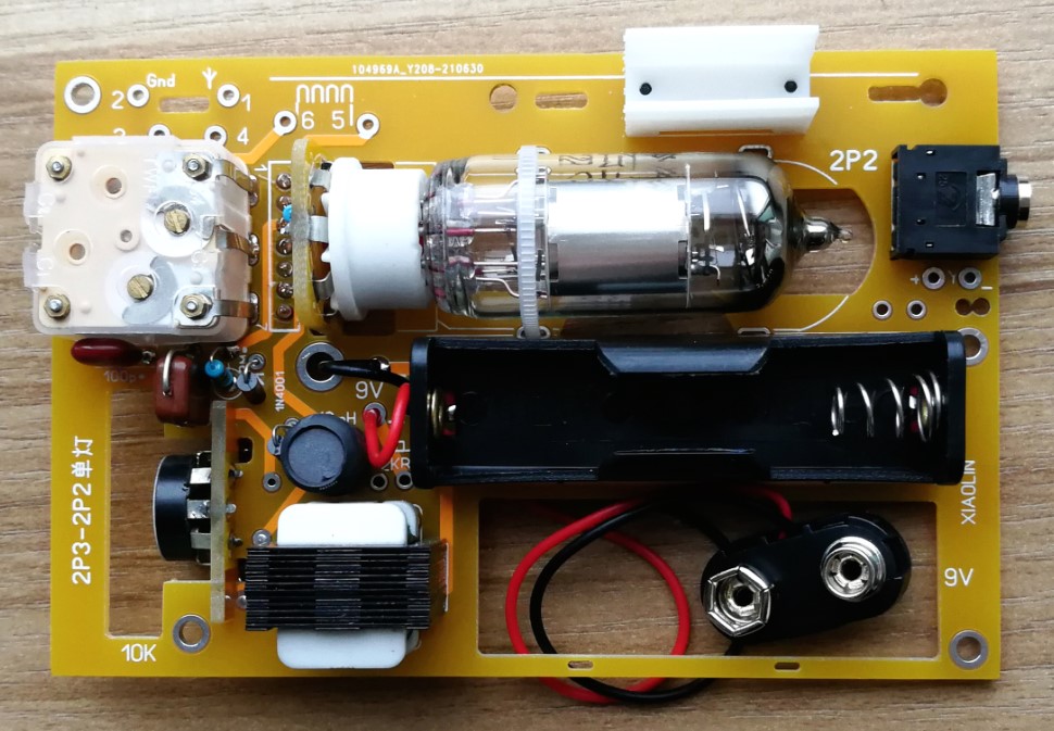
Reference (when assembled):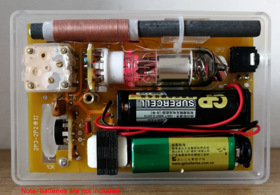
Supporting Circuit Diagram: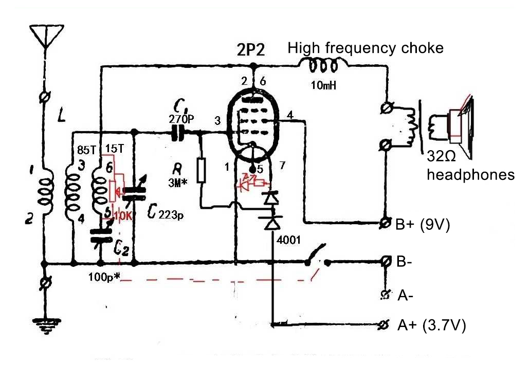
- As shown in the figure, the coil needs to be wound by the user. Elementary 3--4 using about 85 turns of cotton-covered wire.
- Regeneration 5--6 using about 25-35 turns of varnished wire. (Varnished wire should also be used to make antenna coil).
- First weld the 7-pin tube seat to ensure that the bottom surface of the seat is close and flat with the board. After welding, cut off the protruding welding feet.
- Then the LED is soldered. Pay attention to the height when welding, and the top surface should be level with the top of the tube seat to have a better luminous decorative effect.
- Finally, solder the current limiting resistor: cut the lead short, at this time the pad of the resistance surface is welded.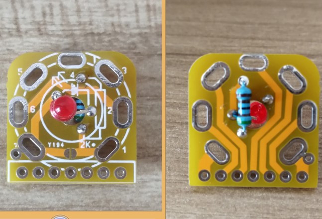
- First weld the small plate of the potentiometer vertically to the main board, and then solder the potentiometer.
- Variable capacitors should be welded after the welding and adjusting of the small plate of the tube seat.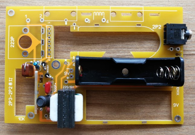
- The tube is first inserted into the seat on the welded small board, and then tied with a cable tie to make it flush with the board.
- The lamp holder board should also be perpendicular to the motherboard, and then solder the pin header of Pin 7.
- The potentiometer switch board and the large plate have 5 large solder joints, the middle 3 points are for potentiometers, and the upper and lower 2 points are for switches.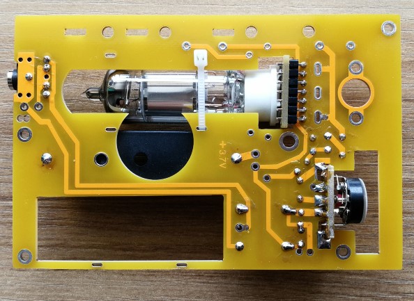
The half-circle pad on the back of the board, the selection of short circuit and no short connection is used to select access and no access.
1.It can be connected to only one antenna and grounded by making 10 turns around the magnetic rod.
2. The 223P of the variable capacitor kit needs to be short-circuited to the variable foot pad so that the two sets are connected in parallel.
3. Only 4 pads are soldered with transformers, 2 pads on a wire, the pad in the middle of the welding is connected to 8Ω, and the pad on the welding edge is connected to 32Ω. When using a high-resistance headphone transformer, the 5 pads are not short-circuited, and the high-resistance solder joint and the headphone holder are directly connected with wires.
4. If the earphone holder is plugged with a 2-core 3.5 to 6.5 high-resistance conversion plug, it is necessary to cut the solder joint of the lower channel to avoid short circuit of the sound signal.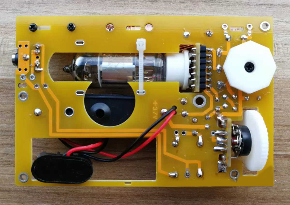
Package Included:
- 1 x Radio Kit
Note:
- Shell is not included.
- Assembling is needed.
 for DIY")
 for DIY")
 for DIY")
 for DIY")
 for DIY")
 for DIY")


