| Quantity | 3+ units | 10+ units | 30+ units | 50+ units | More |
|---|---|---|---|---|---|
| Price /Unit | $14.13 | $13.84 | $13.41 | $12.83 | Contact US |
 Crosbon Imported 3-Core 6mm² OFC Power Cable Soft OFC Speaker Wire (US Standard Plug, 1.5 Meters)
$37.31
Crosbon Imported 3-Core 6mm² OFC Power Cable Soft OFC Speaker Wire (US Standard Plug, 1.5 Meters)
$37.31
 Geekworm 5-in-1 RAB Holder Breadboard Holder ABS Base for Raspberry Pi 5 Ar-duino UNO R3 & Mega 2560
$11.37
Geekworm 5-in-1 RAB Holder Breadboard Holder ABS Base for Raspberry Pi 5 Ar-duino UNO R3 & Mega 2560
$11.37
 Portable Handheld Tesla Coil 3.0 PRO Version 0-500uS 7-level Adjustable Power Pulse Width (2600mAH meets 20000 arcs)
$51.66
Portable Handheld Tesla Coil 3.0 PRO Version 0-500uS 7-level Adjustable Power Pulse Width (2600mAH meets 20000 arcs)
$51.66
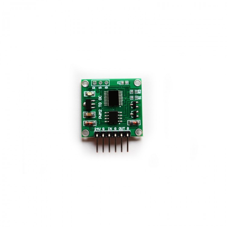
Description:
- PWM to voltage module
- This is a linear conversion module, which is processed by the internal chip to output the PWM data expressed as a voltage signal.
Specification:
- Power supply voltage: 9V ~ 24V
- Signal input voltage range: 4~24V
- Signal input frequency range: 50Hz~10KHz
- Signal input duty cycle range: 0~100%
- Output voltage: 0.00V ~ 5.00V/0.00V ~ 10.00V
- Input method: S1 pad on the circuit board: The default is open circuit, which has not been used yet.
- Output mode: S2 pad on the circuit board: open circuit (output 0.00V ~ 5.00V); short circuit (output 0.00V ~ 10.00V), the default is open circuit.
- Scope of application: remote data acquisition and control equipment;
- Dimensions: (length) 26mm * (width) 23mm * (height) 10mm
10. Module interface:
24V: Positive port of power supply (9V ~ 24V).
G: Power ground interface.
IN: Signal input positive connector.
G: Signal input negative terminal.
OUT: Signal output interface (0.00V ~ 5.00V/0.00V ~ 10.00V).
G: Power ground interface.
Note: When outputting 0.00V ~ 10.00V, the power supply voltage should be 15V.
Output (0.00V ~ 5.00V) Resolution: 0.050V/D (V/per duty cycle)
Output (0.00V ~ 10.00V) Resolution: 0.100V/D (volts/per duty cycle)
Calculate the measured duty cycle formula: (output voltage (V)/resolution) = duty cycle (%).
For example: output (0.00V ~ 5.00V) output is 2.5V
(2.5(V)/0.05) = 50(%).