| Quantity | 3+ units | 10+ units | 30+ units | 50+ units | More |
|---|---|---|---|---|---|
| Price /Unit | $28.96 | $28.37 | $27.48 | $26.30 | Contact US |
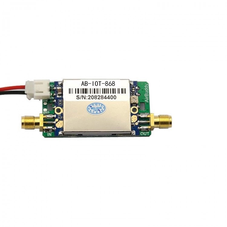
AB-IOT868-SMA 850MHz-930MHz Bi-directional Signal Amplifier Module 5V IoT RFID Transceiving Signal Amplifier
Description:
- The AB-IOT bidirectional signal amplification module is suitable for micro-power wireless products in the frequency range of 850MHz-930MHz, with typical frequencies such as 868MHz/915MHz. The module is only the size of a coin, with simple peripheral circuits and stable operation. It can be applied to wireless data acquisition systems in Europe from 863MHz-870MHz and in the Americas from 902MHz-928MHz.
Features:
- Equipped with an intelligent receiver/transmitter discrimination circuit, it can function normally without the need for front-end devices to provide receiver/transmitter switching control signals.
- The module works by default in the receiving state, amplifying the received signal. When it detects that the front-end device is transmitting a signal externally, it instantly switches to the transmitting amplification state.
- The transmission gain is adjustable, making it convenient to be compatible with wireless devices of different transmission powers.
- The receiving/transmitting link has extremely high isolation, and the receiving link can withstand strong external interference without causing self excitation in the loop.
- Compatible with LORA and various modulation methods such as FSK/ASK/OOK/MSK/GFSK.
- The working frequency range is 850MHz-930MHz
Specification:
- Working frequency: 850MHz - 930MHz
- Receiving gain: 11dB±2dB
- Receiving noise ratio: ≤2.0dB
- Transmitting gain: 5dB - 11dB (±2dB) adjustable
- Threshold for distinguishing between transmitting and receiving switch: -2dBm
- Input power range: 1dBm - 20dBm
- Maximum transmitting power: 31dBm (1.3W)
- Working status indicator:
Receiving status: green light on, blue light off
Transmitting status: blue light on, green light off
TDD working status: blue and green lights flash alternately
- Working voltage: 5V
- Working current: 10mA (±3mA) for RX status; ≤720mA for TX status
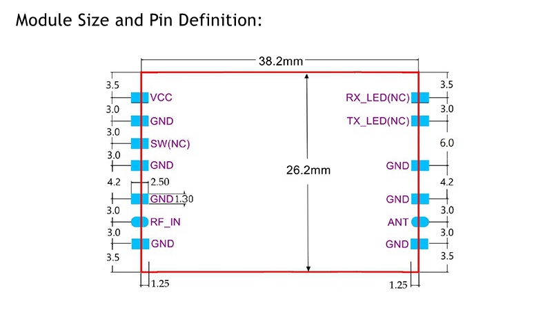
- Product size: 38.2 x 26.2 x 4.5mm
Note:
- To ensure reliable switching, at least 3dB margin should be reserved for the transmission power of the front-end device, that is, the minimum transmission power of the front-end device cannot be lower than 1dBm, otherwise it may cause unstable switching between receiving and transmitting.
- When the module is working, most of the timing is in the receiving state, and the current in the receiving state is about 10mA. When the module switches to the transmitting state and transmits at maximum power, the instantaneous current can reach up to 720mA. Because the transmission timing is generally very short (under normal circumstances, each data packet is at the ms or even us level), the average current during the entire working period is generally not higher than 100mA.
Warning:
- This module is not recommended for applications with constant emission (i.e. constant blue light on)! If it is necessary to work in a constant transmission mode and the transmission power is high (close to 1.3w), there will be a phenomenon of high current and severe heating. At this time, additional heat dissipation measures (such as adding heat sinks or fans) must be added, otherwise the maximum transmission power will automatically decrease due to high temperature, and in severe cases, the amplifier will be burned out.
Transmission gain adjustment method:
- The transmission gain is 5dB when the potentiometer is turned counterclockwise to the bottom.
- The transmission gain is 11dB when the potentiometer is turned clockwise to the bottom.
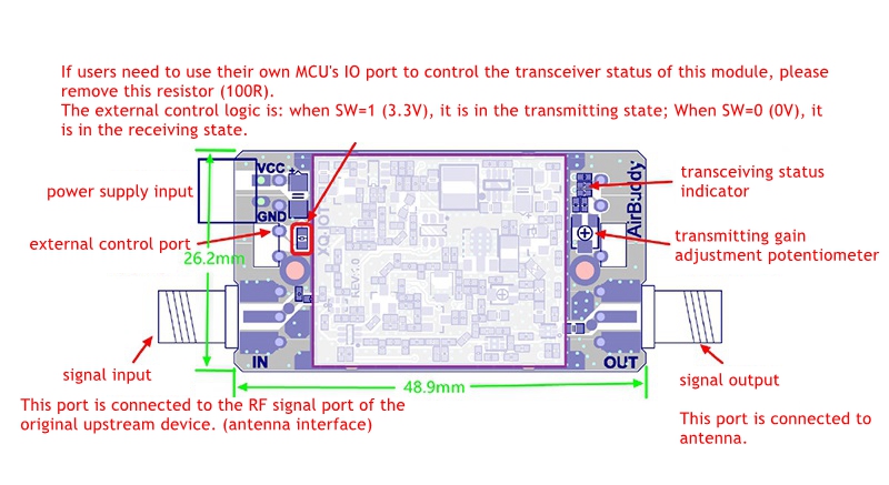
Pin Definition:
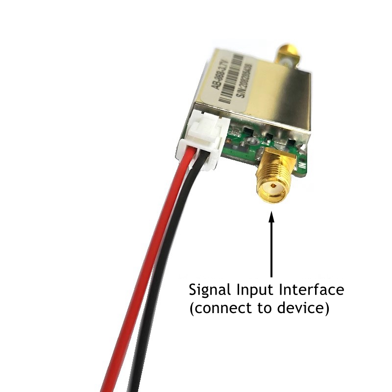
- The RF_IN pin is connected to the RF signal output port of the front-end device/circuit (i.e. to the antenna port of the front-end device/circuit).
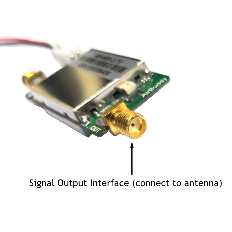
- Connect the ANT pin to the antenna.
- When transmitting at full power, the instantaneous current can reach over 700mA. To ensure stable power supply, please connect a large capacity capacitor (with a capacity not less than 220uF) to the VCC port.
- Pin names marked with (NC) are reserved for specific applications, while ordinary applications only require the NC pin to be suspended.
- The receiver/transmitter switching can be controlled by external circuits (i.e. the front-end device control circuit provides the receiver/transmitter switching control logic level to control the receiver/transmitter switching of this module), and the SW pin is reserved for external control functions. Please operate the external control according to the requirements (Reference Application).
Reference Application:
- The module is easy to use, just provide the corresponding power supply to the VCC pin to work normally.
- 5V power supply version: Connect the power port to a 5V power supply.
- The following figure shows the functional test board diagram and interface function indicators (functional test board size of 48.9mmx26.2mm):