| Quantity | 3+ units | 10+ units | 30+ units | 50+ units | More |
|---|---|---|---|---|---|
| Price /Unit | $15.44 | $15.12 | $14.65 | $14.02 | Contact US |
 JD-118 +/-3.5dB High Precision Digital Noise Meter 30-130dB Sound Level Meter with 2.17-inch LCD Screen
$25.39
JD-118 +/-3.5dB High Precision Digital Noise Meter 30-130dB Sound Level Meter with 2.17-inch LCD Screen
$25.39
 JD-105 +/-1.5dB High Precision Digital Noise Meter 30-130dB Sound Level Meter with 2.17-inch LCD Screen
$25.39
JD-105 +/-1.5dB High Precision Digital Noise Meter 30-130dB Sound Level Meter with 2.17-inch LCD Screen
$25.39
 JD-861 Digital Handheld Temperature and Humidity Tester Wet Bulb Temperature and Dew Point Temperature Measurement
$22.23
JD-861 Digital Handheld Temperature and Humidity Tester Wet Bulb Temperature and Dew Point Temperature Measurement
$22.23
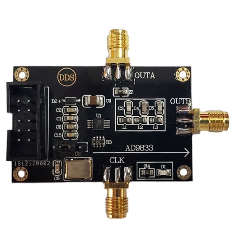
AD9833 DDS Signal Generator Module Signal Source Triangle Wave Sine Wave Square Wave Generator
Attention:
- The module's interfaces are clear and the performance is stable. Please use the schematic diagram provided by us for functional verification under the corresponding experimental conditions.
- The basic parameters of this module are all described in the following description, and the module information PDF file and routine source code are provided. Project files are not provided. Buyers can consult customer service if they have operation problems.
- Before using the module, please read the details of this module to understand the power supply and usage restrictions to avoid damage to the module due to improper operation.
- We provide real module parameters, functions and pictures, all modules are tested and shipped.
Module Parameters:
- Module model: AD9833
- Module type: digital synthesis frequency
- Module power supply: DC-5V
- Module current: 10mA (MAX.) [Normal drive current 8mA (TYP.)]
- Module communication protocol: SPI serial
- Module provides example: STM32F103RC
- Example platform: STM32F103X- (For KEIL5 version source code)
- Module system main frequency: 25MHz (MAX.)
- DAC resolution bits: 10 bits
- Phase accumulator bits: 28 bits
- Module output interface: SMA (24-hour plating smoke anti-oxidation)
- Module output signal: sine wave, square wave, triangle wave (sine wave with 9MHz low-pass filter.)
- Module output channel: 2 channels differential (B channel with filter, A channel direct output)
- Module signal characteristics: sine wave without coupling (output with its own DC component, please add a DC block when connecting to radio frequency equipment. You can also directly use an oscilloscope to measure.)
- The highest main frequency output sine wave signal range: 1Hz-9MHz
- The highest frequency output square wave signal range: 1Hz-1MHz (square wave duty cycle is not adjustable.)
- Output amplitude: sine wave 260mVpp (MAX.). Square wave 3.3Vpp (the amplitude of sine wave decreases with increasing frequency, and the waveform of square wave changes with increasing frequency)
- Output impedance: 200 ohms
- Module features: multiple (high-performance DDS sine wave signal generator, high-order elliptic filter, low-noise voltage regulator chip, etc.)
- Module application: Various (frequency signal generation, sine wave, square wave signal generation, sensor excitation)
- Module weight: 12.7g
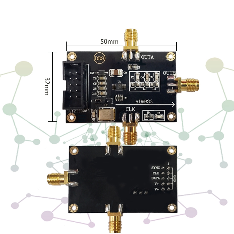
- PCB size: 70*50*12 mm (LxWxH)
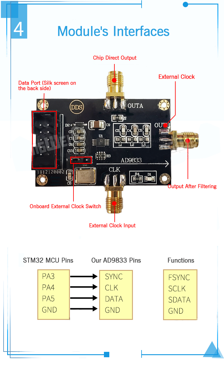
- Module interface type: SMA signal output and external clock input, DC5.5 power socket, XH2.54-10PIN double-row pin data interface
Module Description:
AD9833 is a low-power, programmable waveform generator that can generate sine wave, angular wave and square wave output.
Various types of detection, actuation, and time domain reflectometry (TDR) applications require waveform generators. The output frequency and phase can be programmed through software, which is easy to adjust. No external components are required. The frequency register is 28 bits; the clock rate is 25MHz, which can achieve a resolution of 0.1H. Similarly, when the clock rate is 1MHz, AD9833 can achieve a resolution of 0.004Hz.
Precautions:
(1) The module is a low-power module, and power supply does not exceed 5.5V.
(2) The module is a high-precision device. In order to avoid unnecessary interference, it is recommended to use a linear power supply.
(3) It is recommended to use SMA to BNC cable for input signal, and directly observe the effect with an oscilloscope. Poor contact or poor quality cables may cause signal attenuation or excessive noise.
(4) The code is only used for main control board, no MCU tutorial is provided, and additional functions need to be developed by yourself.
(5) If you need to simply test the function of the module, it is recommended to use it with our control board. Power the DDS module first, and then power the control board to generate waveform, long press the middle button to switch functions.
Package Included:
- 1 x Signal Generator Module