| Quantity | 3+ units | 10+ units | 30+ units | 50+ units | More |
|---|---|---|---|---|---|
| Price /Unit | $33.34 | $32.66 | $31.64 | $30.28 | Contact US |
 Black 3D-Printed Mini ESP32 Marauder Development Board Positioning Module with 1.44-inch Screen
$33.36
Black 3D-Printed Mini ESP32 Marauder Development Board Positioning Module with 1.44-inch Screen
$33.36
 White 3D-Printed Mini ESP32 Marauder Development Board Positioning Module with 1.44-inch Screen
$33.36
White 3D-Printed Mini ESP32 Marauder Development Board Positioning Module with 1.44-inch Screen
$33.36
 MPSoC XCZU19EG-F V0.3 AMR+FPGA Development Board Kit QSFP28 10Gbps Ethernet PCIE3.0 Support for Windows/Linux Systems
$1,537.98
MPSoC XCZU19EG-F V0.3 AMR+FPGA Development Board Kit QSFP28 10Gbps Ethernet PCIE3.0 Support for Windows/Linux Systems
$1,537.98
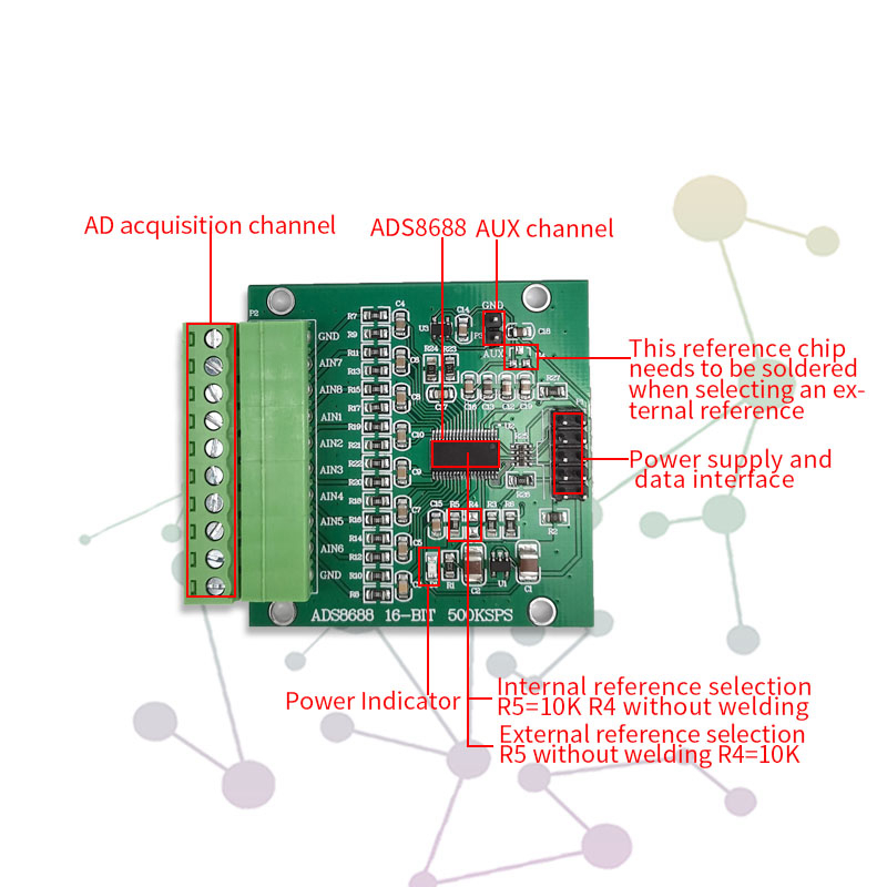
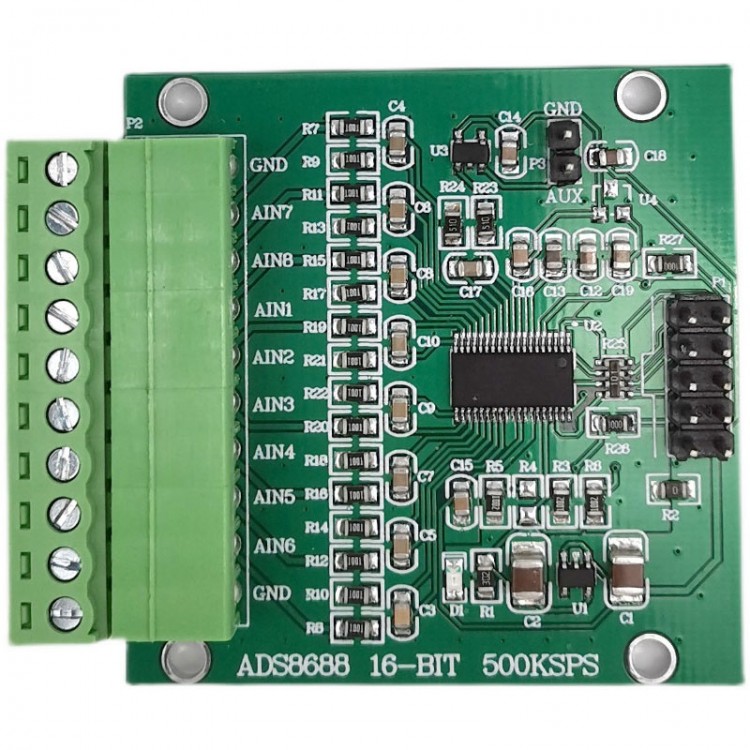
ADS8688 16-Bit 500KSPS Data Acquisition Module Single/Bipolar Input 8-channel SAR/ADC Module
Attention:
(1) The module interface of our store is clear and the performance is stable. Please use the information provided by our store to do functional verification under the corresponding experimental conditions.
(2) The basic parameters of this module are in the details page, and the module information PDF file and the source code of the routine are provided. Project files are not provided. If you have any operational problems, please consult customer service.
(3) Before using the module, please read the details page of this module to understand the power supply and usage restrictions, so as to avoid damage to the module due to improper operation.
(4) All modules in our shop guarantee to provide real module parameters, functions and pictures, and all modules are tested and shipped.
Module Description:
ADS8688 is an 8-channel integrated data acquisition system, which is based on a 16-bit successive approximation (SAR) analog-to-digital converter (ADC) with a throughput of up to 500kSPS during operation. These devices provide integrated analog front-end circuits (overvoltage protection up to ±20V) for each input channel. An 8-channel multiplexer that supports automatic and manual scanning modes, and an on-chip 4.096V reference voltage with low temperature drift. When powered by a single 5V analog power supply, each input channel on the device can support actual bipolar input ranges of ±10.24V, ±5.12V, and ±2.56V, and unipolar input ranges of 0V to 10.24V and 0V to 5.12V. The gain of the analog front end in all input ranges has been precisely fine-tuned to ensure high DC accuracy. The selection of the input range can be programmed by software, and the selection of the input range of each channel is independent of each other. The device provides a constant resistive input impedance of 1MΩ.
Module Parameters:
- Module model: ADS8688
- Module type: ADC module
- Module power supply: 5V
- Static power consumption: <2.2mA (for reference only)
- Module communication protocol: SPI serial
- Input impedance: 1MΩ
- Number of input channels: 8
- Reference voltage: internal 4.069V by default (weldable SOT-23 package external input reference)
- Input range: Bipolar: ±10.24V, ±5.12V and ±2.56V. Unipolar: 0V to 10.24V, and 0V to 5.12V (software switching range)
- Resolution: 16 bits
- Chip maximum sampling rate: 500kSPS (total throughput)
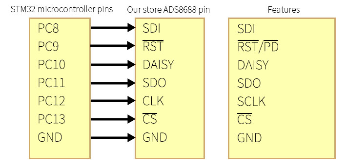
- The module provides a routine: STM32F103RBT6 (analog SPI)
- Module features: multiple (programmable gain amplifier (PGA) integrated inside the chip, and on-chip reference voltage with low temperature drift, constant resistive input impedance)
- Module application: multiple (power automation, protection repeater, factory automation and process control, etc.)
- Module weight: 13g
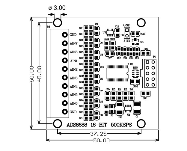
- PCB size: 50x50mm (LxW)
- Module interface: 3.81-8P socket, XH2.54 double row pin
Precautions:
(1) The module is a low-power module, and it is recommended that the power supply does not exceed 5.25V.
(2) Since the module is a high-precision device, in order to avoid unnecessary interference, it is recommended to use a linear power supply.
(3) It is recommended that the input and output signal lines be as short as possible. If the signal line is too long, it is easy to introduce noise signals. Poor contact or poor quality cables may cause signal attenuation or excessive noise.
(4) The delivered code is only for the main control board of our store. The program is fully commented and does not explain the program. Functions other than the detailed display need to be developed by yourself.
(5) If you need to test the function of the module simply, it is recommended to use it with the control panel of our store. After the correct wiring, power the control panel to achieve signal acquisition and display.
Package Included:
- 1 x ADS8688 Module
FAQ:
Q: Can the module measure negative voltage?
A: Yes, when the range is selected as bipolar, negative voltage can be measured.
Q: Is the maximum value 65535? How to convert to voltage?
A: When the selected range is bipolar, 0V corresponds to 32767, so V=(ADC value-32767)*range/65535; when the range is unipolar, there is no need to subtract 32767.
Q: Does each channel independently have a 500kSPS data update rate?
A: The maximum total throughput of ADS8688 is 500kSPS. The throughput of each channel depends on the number of channels selected in the multiplexer scan sequence. If only two channels are selected, the throughput of each channel is equal to 250kSPS, if four channels are selected, it is equal to 125kSPS per channel, and so on.
Q: What is the difference between AUX and other channels?
A: The AUX channel is directly connected to the high-precision 16-bit ADC through the multiplexer inside the chip; because there is no front-end PGA, the AUX channel only supports a unipolar input range from 0V to VREF.
Q: Is it possible to configure the input range independently for each channel?
A: Each channel of ADS 8688 has PGA, so the input range and polarity can be configured independently.
Q: For example, if you give a voltage: 2.1234V and let the module keep collecting, what is the result? Will the value fluctuate?
A: The data must be fluctuating. This is not determined by a single condition. Factors such as power supply ripple noise and excessive wire length will affect it.
Q: ADS8688 is not accurate in collecting small voltage signals. What is the situation?
A: It may be that the range configuration is too large. You can set the chip range range (PGA) reasonably according to the signal range you want to collect.
Q: After the module is driven normally, the pins that are not connected to voltage also show voltage. Is it normal?
A: By default, the module collects 8 channels all the time, and the floating voltage on the pin is also collected when there is no voltage connected. The pin can be directly grounded, which is 0 voltage.