| Quantity | 3+ units | 10+ units | 30+ units | 50+ units | More |
|---|---|---|---|---|---|
| Price /Unit | $10.48 | $10.26 | $9.94 | $9.51 | Contact US |
 RT-Thread ART-Pi II High Performance Development Board STM32H7R7 Core Board with 4GB EMMC + A Base Board
$56.49
RT-Thread ART-Pi II High Performance Development Board STM32H7R7 Core Board with 4GB EMMC + A Base Board
$56.49
 RT-Thread ART-Pi II High Performance Development Board STM32H7R7 Core Board + A Base Board
$48.71
RT-Thread ART-Pi II High Performance Development Board STM32H7R7 Core Board + A Base Board
$48.71
 RT-Thread RK3506B Commercial Grade Core Board 256MB DDR+256MB Flash Support for Linux/Ubuntu/OpenEuler
$25.28
RT-Thread RK3506B Commercial Grade Core Board 256MB DDR+256MB Flash Support for Linux/Ubuntu/OpenEuler
$25.28
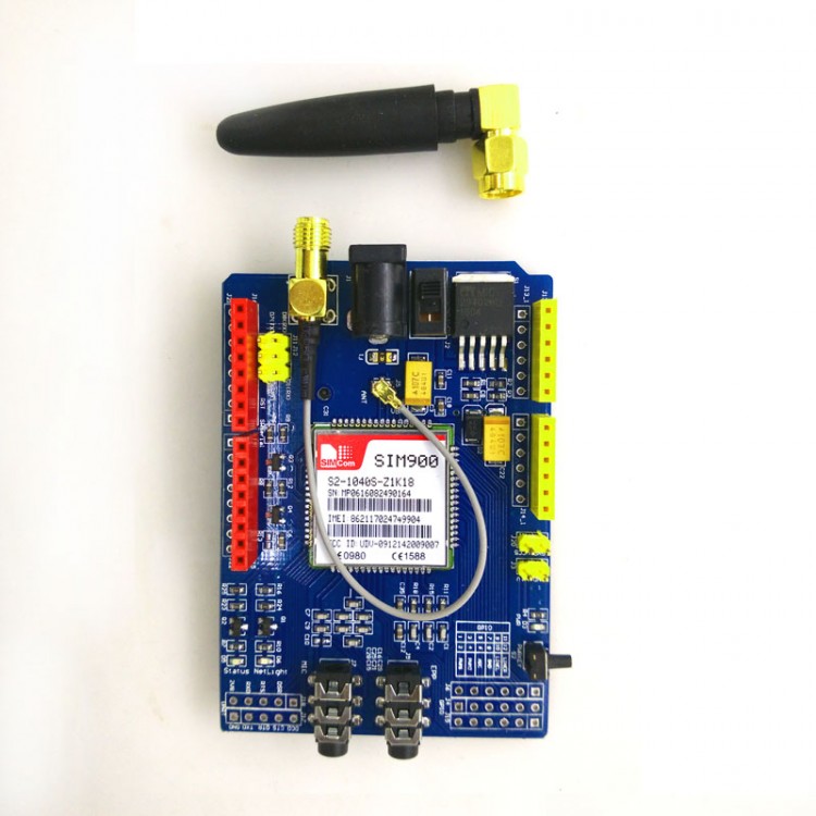
SIM900 Module For Arduino GPRS Shield 4 Frequency Development Board GSM GPRS SMS Wireless Data TC35i
Description:
The GPRS Shield is based on SIM900 module from SIMCOM and compatible with Arduino and its clones. The GPRS Shield provides you a way to communicate using the GSM cell phone network. The shield allows you to achieve SMS, MMS, GPRS and Audio via UART by sending AT commands (GSM 07.07 ,07.05 and SIMCOM enhanced AT Commands). The shield also has the 12 GPIOs, 2 PWMs and an ADC of the SIM900 module(They are all 2V8 logic) present onboard.
1. Provide 2 kinds of antenna interfaces, compatible with various needs. This product is shipped with an antenna, and the antenna has an extension cable, so it is compatible with 2 interfaces.
2. SIM900 can be set via jumper cap and connected to any 2 pins of Arduino from D0 to D7, not only the hardware UART of D0D1.
3. Debug toggle switch, you can set the DEBUG port of SIM900 to connect to Arduino or connect to PC through ATMEGA8U2 / FT232 on Arduino for debugging.
4. The audio and microphone ports are led out.
5. The multiple IO ports of SIM900 are led out. If necessary, you can use a Dupont cable to connect the pins-refer to the schematic diagram and datasheet for specific pins.
6. 3 status indicator lights, and 3 buttons-the power on button can be used to power on SIM900 by using the Arduino pin control to reach the software.
7. 3.3V and 5V automatic level compatible, it can adapt to 3.3V or 5V main control board, support leaf maple and Chipkit and other platform development boards of 3.3V.
Features:
-Quad-Band 850 / 900/ 1800 / 1900 MHz - would work on GSM networks in all countries across the world.
-GPRS multi-slot class 10/8.
-GPRS mobile station class B.
-Compliant to GSM phase 2/2+.
-Class 4 (2 W @ 850 / 900 MHz).
-Class 1 (1 W @ 1800 / 1900MHz).
-Control via AT commands - Standard Commands: GSM 07.07 & 07.05 Enhanced Commands: SIMCOM AT Commands.
-Short Message Service - so that you can send small amounts of data over the network (ASCII or raw hexadecimal).
-Embedded TCP/UDP stack - allows you to upload data to a web server.
-RTC supported.
-Selectable serial port.
-Speaker and Headphone jacks.
-Low power consumption:1.5mA(sleep mode).
-Industrial Temperature Range: -40°C to +85 °C.
Specifications:
Application Ideas
-M2M (Machine 2 Machine) Applicatoions.
-Remote control of appliances.
-Remote Weather station or a Wireless Sensor Network.
-Vehicle Tracking System with a GPS module.
Instructions for Use:
-The computer can debug USB-TL. This version of 5-26V2A current power supply, recommended 5V voltage 2A current. After plugging in the Arduino motherboard, we must also connect our 5-26V2ADC power supply. The reason is that the GPRS Shield's boot current and maximum peak current need to be 2A at the maximum, but the USB port cannot provide such a large current, so it must be connected to a power supply device. The pin of the other power supply port leads to 3.7-4.5V power supply suitable for lithium battery power supply. Serial port, compatible with arduino microcontroller. The TL serial port is compatible with 3.3 and 5V microcontrollers.
-Make sure your SM card is not locked.
-The baud rate of GPRS Shield communication is preferably 19200bps8-N-1 (GPRS Shield automatically matches the baud rate by default).
Package Included:
1 Set Module Board
Notes:
1. Make sure your SIM card is unlocked.
2. The product is provided as is without an insulating enclosure. Please observe ESD precautions specially in dry (low humidity) weather.
3. The factory default setting for the GPRS Shield UART is 19200 bps 8-N-1. (Can be changed using AT commands).
4. Power select - select the power supply for GPRS shield(external power or 5v of arduino).
5. Power jack - connected to external 4.8~5VDC power supply.
6. Antenna interface - connected to external antenna.
7. Serial port select - select either software serial port or hareware serial port to be connected to GPRS Shield.
8. Hardware Serial - D0/D1 of Arduino.
9. Software serial - D7/D8 of Arduino.
10. Status LED - tell whether the power of SIM900 is on.
11. Net light - tell the status about SIM900 linking to the net.
12. UART of SIM900 - UART pins breakout of SIM900.
13. Microphone - to answer the phone call.
14. Speaker - to answer the phone call.
15. GPIO,PWM and ADC of SIM900 - GPIO,PWM and ADC pins breakout of SIM900.
16. Power key - power up and down for SIM900.