| Quantity | 3+ units | 10+ units | 30+ units | 50+ units | More |
|---|---|---|---|---|---|
| Price /Unit | $9.15 | $8.97 | $8.69 | $8.31 | Contact US |
 Sipeed Black Version SLogic Combo 8 Multifunctional Logic Analyzer 8-Channel UART DAPLink CKLink Debugger Tool
$18.87
Sipeed Black Version SLogic Combo 8 Multifunctional Logic Analyzer 8-Channel UART DAPLink CKLink Debugger Tool
$18.87
 Sipeed White Version SLogic Combo 8 Multifunctional Logic Analyzer 8-Channel UART DAPLink CKLink Debugger Tool
$18.87
Sipeed White Version SLogic Combo 8 Multifunctional Logic Analyzer 8-Channel UART DAPLink CKLink Debugger Tool
$18.87
 High End Version JTAG SWD Programmer MCU Debugger STM32 Emulator Debug Tool Set for Jlink V11
$49.55
High End Version JTAG SWD Programmer MCU Debugger STM32 Emulator Debug Tool Set for Jlink V11
$49.55
CH341A USB Programmer BIOS Programmer Flasher Kit with Test Clip Adapter for 24 25 Series Chips
Download Driver:
Link for http://www.wch.cn/download/CH341SER_EXE.html
Product Introduction:
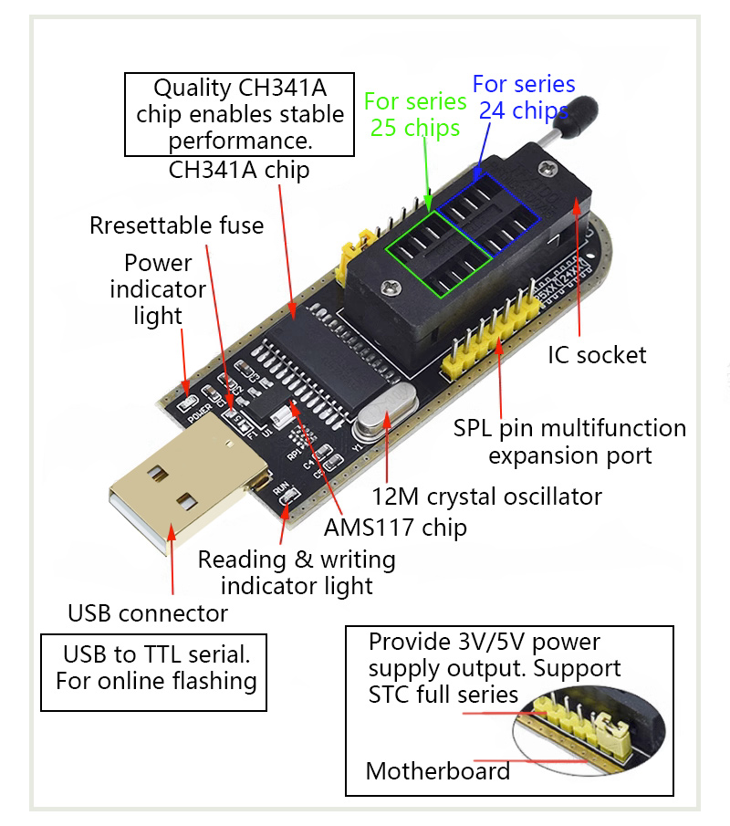
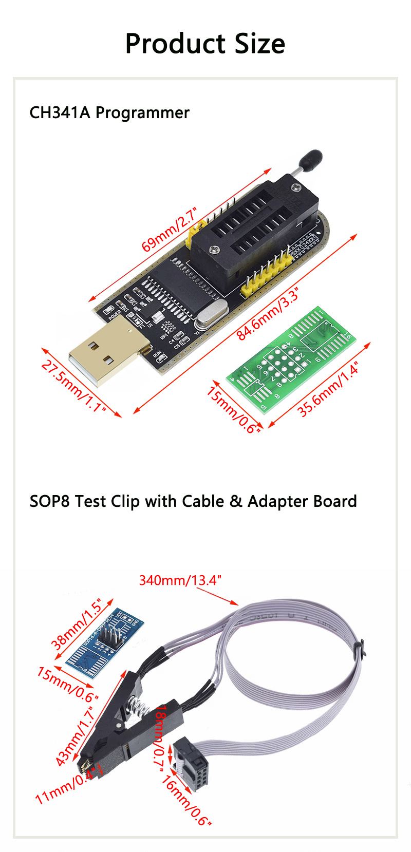
1. CH341A Programmer
- Support parallel port: support the parallel port of USB printers, EPP and MEM
- Support serial port: support USB to UART, I2C and SP interfaces
- Output voltage: The output voltage signal level can be selected: 3.3V or 5V
- On-board power indicator, reading-writing indicator and on-board 506MA resettable fuse
Features:
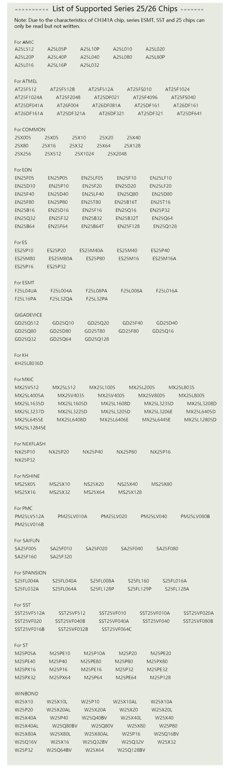
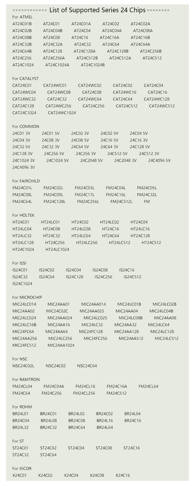
- Support series 24 and 25 chips (read the lists below)
- Support USB to TTL online flashing (if you need a cable for Dupont, please purchase separately)
- The board with SPI pin corresponding to MSI JSP11 interface (special cable should be purchased separately)
- Support MCU (for STC) online program downloading (if you need a cable for Dupont, please purchase separately)
- Provide 5V and 3.3V power output. Support all popular operating systems for WINDOWS, including 32-bit and 64-bit systems
- Designed with 506MA resettable fuse
- Support 24EEROM
- Stable CH341A chip
- It supports 25 SPI FLSAH
- Support MCU program downloading
- Support online flashing
2. SOP Test Clip with Cable & Adapter Board:
- It supports chips with 1.27mm pitch, i.e. full series of SOP8 wide and SOP narrow to DIP-8.
- It is suitable for SOP8 chips in 200MIL packages and SOP8 chips in narrow 150MIL packages.
How to use:
Clamp a chip with the clip, and add a voltage of 3.3V to the clip pin corresponding to the 8th pin of the chip. Generally, the 3.3V power supply has two wires, then VCC corresponds to the clip, and the other wire is directly grounded.
Attention:
When using a clip to clamp a chip, do not force it down. Open the clamp, and clamp the chip from the left and right sides of the chip. When removing the chip, you can't pull it out directly, you must first separate the clip from the left and right, and then take out the clip. In this way, the operation will basically not damage the tip of the clamp. When encountering a programmer with a protected function, the clip cannot be used at normal voltage, and a voltage of 3.3V needs to be added at this moment.
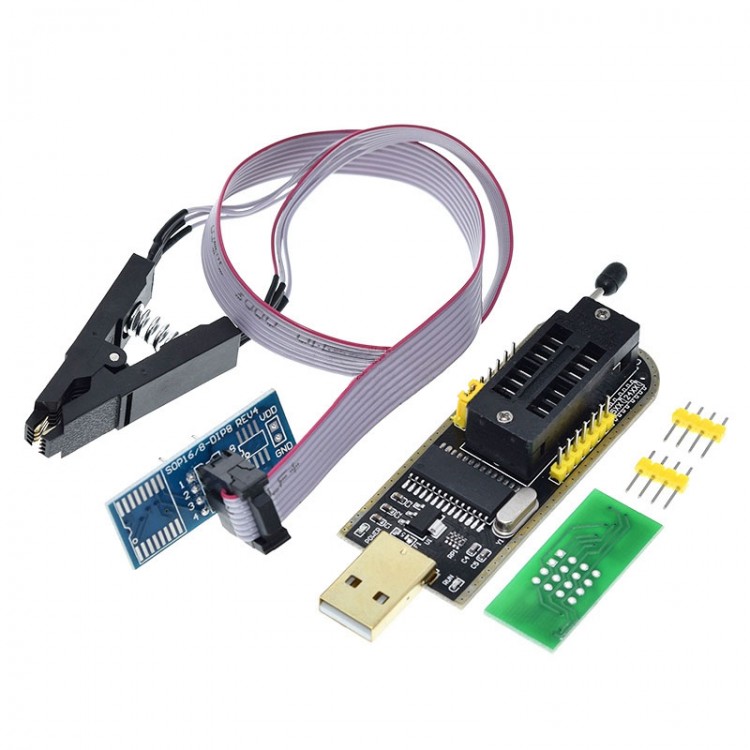
Package Included:
- 1 x Programmer
- 1 x SOP8 Test Clip with Cable
- 1 x 8Pin to 16Pin Adapter Board
- 1 x Green Board
- 2 x 4P Pin Headers


")
