| Quantity | 3+ units | 10+ units | 30+ units | 50+ units | More |
|---|---|---|---|---|---|
| Price /Unit | $69.59 | $68.17 | $66.04 | $63.20 | Contact US |
 ANNOY TOOLS 4.0 3-Axis CNC Controller Board + Offline Controller 1.8" Screen for CNC/Laser Engravers
$42.30
ANNOY TOOLS 4.0 3-Axis CNC Controller Board + Offline Controller 1.8" Screen for CNC/Laser Engravers
$42.30
 ANNOY TOOLS 4.0 3-Axis USB CNC Controller Board for 2-Axis Laser Engravers or 3-Axis CNC Engraver
$23.61
ANNOY TOOLS 4.0 3-Axis USB CNC Controller Board for 2-Axis Laser Engravers or 3-Axis CNC Engraver
$23.61
 F2300BT 2-Axis CNC Motion Controller Support Torch Height Control for Fangling CNC Flame Plasma Cutting Machines
$510.28
F2300BT 2-Axis CNC Motion Controller Support Torch Height Control for Fangling CNC Flame Plasma Cutting Machines
$510.28
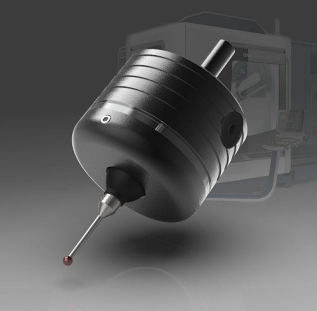
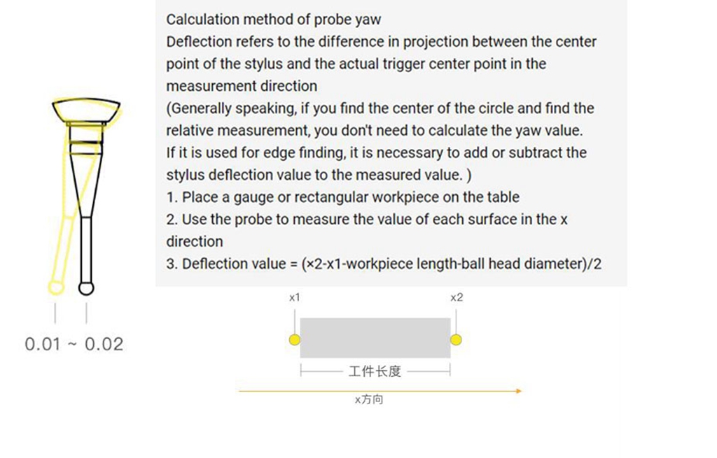
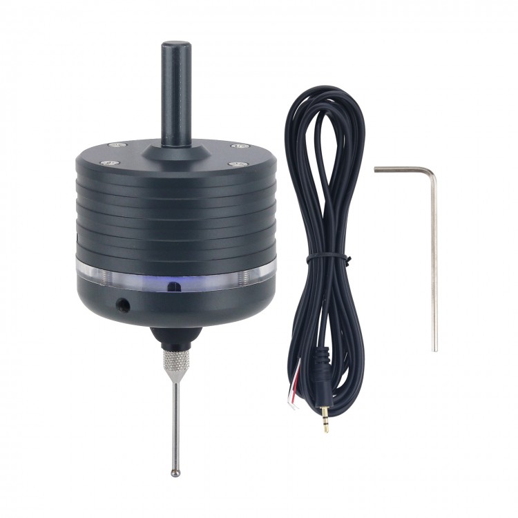
CNC 3D Edge Finder Milling Machine 3D Edge Finder Photoelectric sub-rod grb with a Tungsten Steel Probe
Features:
- The repeatability is 0.01.
- It can measure insulated workpieces.
- The probe signal NPN does not include the system wiring, you have to read the system manual wiring by yourself. Generally, support the tool setting instrument.
- Without wiring, it can be used as a photoelectric splitter.
Parameter:
- Probe length: 20mm
- Clamping diameter: 6mm
- Clamping length: <20mm
- Repeatability: 0.01mm
- XY swing pair: 3mm (it will be damaged if it exceeds the stroke)
- Z pendulum pair: 1.5mm (it will be damaged if it exceeds the stroke)
- Battery: Lithium battery (online automatic charging)
- Offline work: support (can be used as a photoelectric splitting rod)
- Connection work: support (can be used with the system for automatic centering)
- Connection method: distribution data line
- Probe: Φ1 tungsten steel
- Probe: Φ1.5 ruby
- Waterproof rating: IP43 (you can work under the environment of spraying coolant if you are not hungry)
- Working voltage: 6-30v (overpressure burns, low voltage cannot work)
Common problems and improvement methods:
- Data line connection definition:
The red wire is IO (signal), the white wire is GND, and the yellow wire is OV (GND).
- Whether to turn on the spindle speed during detection:
A. The edge finder is designed to withstand a maximum rotation of 600 rpm. High-speed rotation will damage the edge finder.
B. When the data line is connected for automatic detection, the spindle cannot be opened, and the rotation will break the data line and damage the edge finder.
C. When the data line is not connected, and it is simply used as an acousto-optic centering rod, it is also possible to turn on the main shaft to rotate at a speed of 600 rpm/min. Or probing directly without opening the spindle.
- How to judge whether the home position of the edge finder is accurate after the trigger signal?
After the edge finder is installed on the chuck and the meter is turned to 0, push the probe by hand. After the probe returns to its position automatically, rotate the edge finder to see if the value of the meter is a constant value.
- Why is the concentricity different after the precise edge finder is reinstalled on the spindle and the chuck?
Each time the edge finder is reinstalled, it is affected by the concentricity of the spindle and the concentricity of the chuck. The concentricity deviation of the spindle and the chuck will cause the concentricity of the edge finder probe to shift.
- How to improve the detection accuracy in the case that the CNC system of machine tool mechanical structure accuracy cannot be further improved.
A. Rotate centering through the spindle at a speed of 600 rpm (this method can only be used for offline and unconnected work. If you need to rotate the edge finder for automatic centering detection, you can purchase a wireless edge finder to achieve)
B. The deviation of the spindle and the chuck can be improved by making the edge finder adjustment 0 position mark on the spindle and the chuck, and the edge finder is fixed in the same position and direction relative to the chuck and the spindle every time it is installed. (The most fundamental solution is to improve the accuracy of the spindle and chuck)
C. The signal processing response time of the edge finder is fixed at about 0.0005 ± 0.0001s, but the delay consistency of various grades of numerical control systems and supporting circuits is quite different. When the probe is approaching the measured surface, try to reduce the axis movement speed, which can reduce the error caused by the delay consistency problem.
Package Included:
- 1 x 3D Edge Finder
- 1 x USB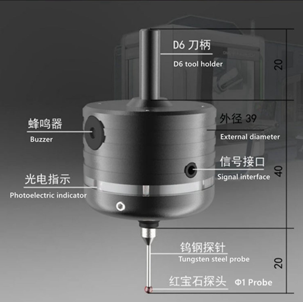
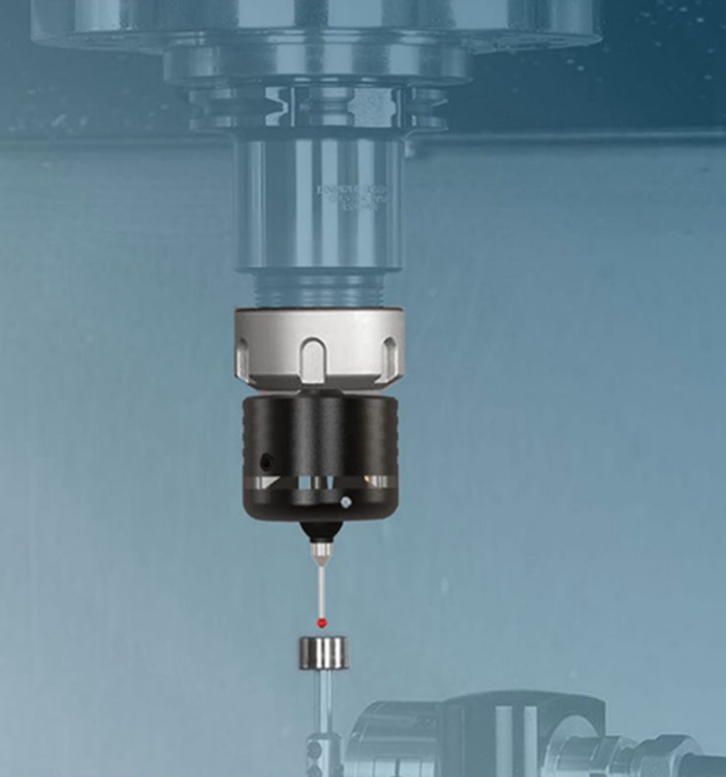
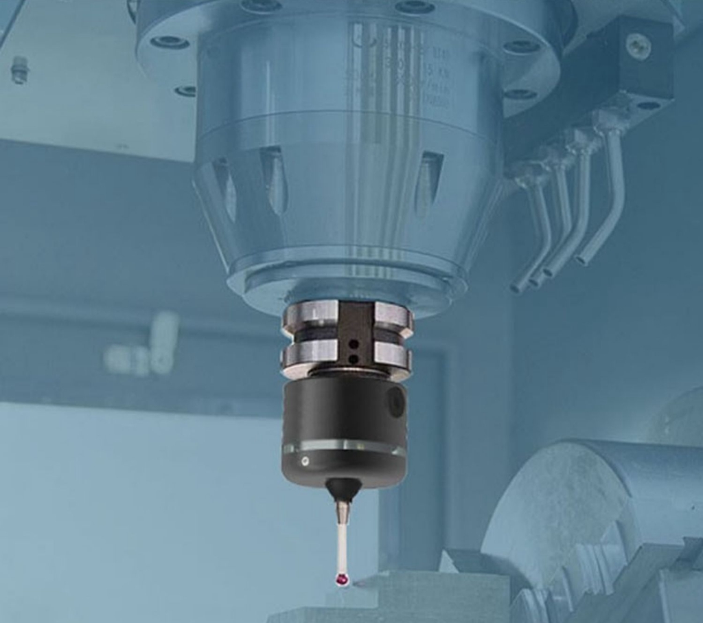


 for CNC Milling Machine Tool Checking Instrument")
 for CNC Milling Machine Tool Checking Instrument")


