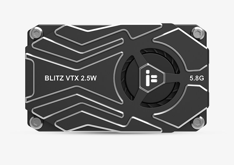
iFlight BLITZ Whoop 5.8G 2.5W High Power VTX Module Built-in Microphone for FPV Drones
Couldn't load pickup availability


Reminder:
- When installing the VTX module, there should be space left to ensure air convection around and to ensure module heat dissipation. Otherwise, the module overheating protection will activate, reduce power transmission, or even turn off power transmission.
- It is recommended to ensure the correct voltage range and positive and negative poles before connecting the power supply to avoid burning out the components.
- It is recommended to ensure that the RF output terminal has an antenna installed before connecting the power supply, which can extend the service life of the module.
- Please read the instruction manual carefully before use and ensure correct wiring to extend the service life of the module.
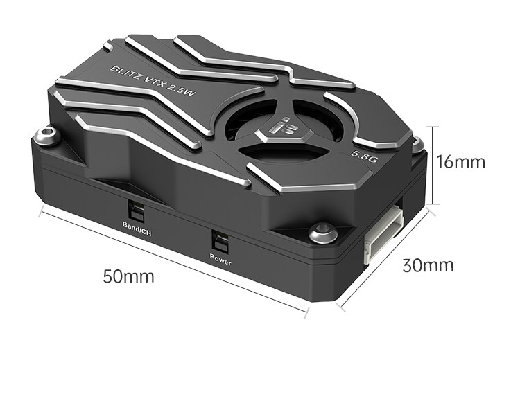
Frequency Band and Channel Buttons:
- Long press for 2 seconds - BAND: LED flashes to indicate frequency range A to R, long press for 2 seconds to switch frequency range.
- Short press - blue (CH): LED light stays on to indicate channels CH1 to CH8, short press to switch channels.
Power Button:
- Press and hold for 2 seconds to enter or exit PIT mode. The green LED is constantly on, indicating entry into PIT mode.
- Short press - green (output power); The flashing LED light indicates the image transmission output rate. Short press to change the output power. Flashing once = 25mW, flashing twice = 400mW, flashing three times = 1000mW, flashing four times = 2500mW.
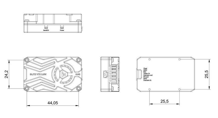
Specification:
- Transmission power: PIT/25mW/400mW/1000mW/2500mW
- Installation hole: 25.5 x 25.5mm, diameter of 1.6mm
- Outer frame size: 50 x 30 x 16mm
- Net weight: 32g
- Image transmission protocol: IRC Tramp
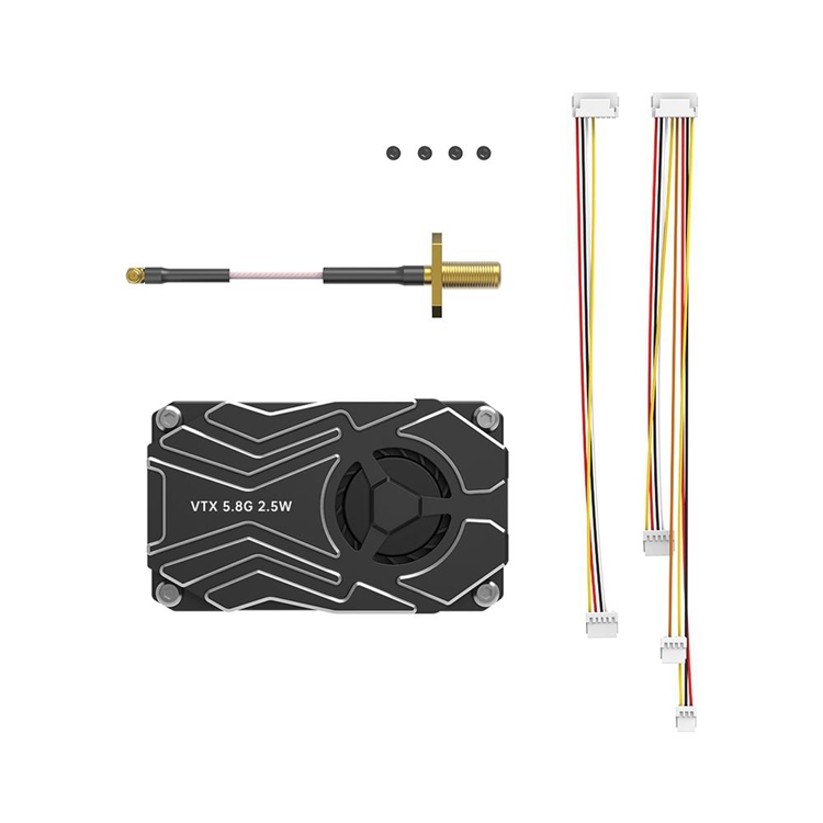
Package Included:
- 1 x VTX Module
- 1 x Accessory Pack