| Quantity | 3+ units | 10+ units | 30+ units | 50+ units | More |
|---|---|---|---|---|---|
| Price /Unit | $78.96 | $77.35 | $74.93 | $71.71 | Contact US |
 JD-118 +/-3.5dB High Precision Digital Noise Meter 30-130dB Sound Level Meter with 2.17-inch LCD Screen
$25.39
JD-118 +/-3.5dB High Precision Digital Noise Meter 30-130dB Sound Level Meter with 2.17-inch LCD Screen
$25.39
 JD-105 +/-1.5dB High Precision Digital Noise Meter 30-130dB Sound Level Meter with 2.17-inch LCD Screen
$25.39
JD-105 +/-1.5dB High Precision Digital Noise Meter 30-130dB Sound Level Meter with 2.17-inch LCD Screen
$25.39
 JD-861 Digital Handheld Temperature and Humidity Tester Wet Bulb Temperature and Dew Point Temperature Measurement
$22.23
JD-861 Digital Handheld Temperature and Humidity Tester Wet Bulb Temperature and Dew Point Temperature Measurement
$22.23
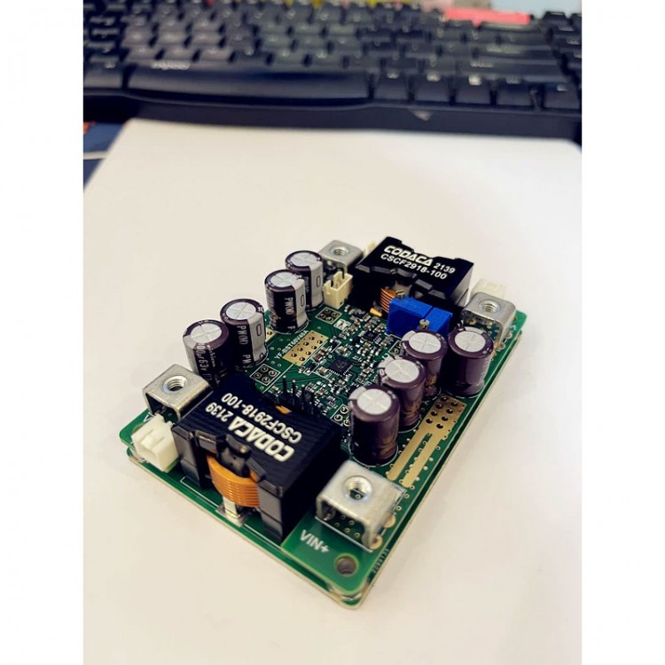
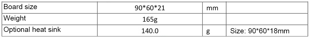
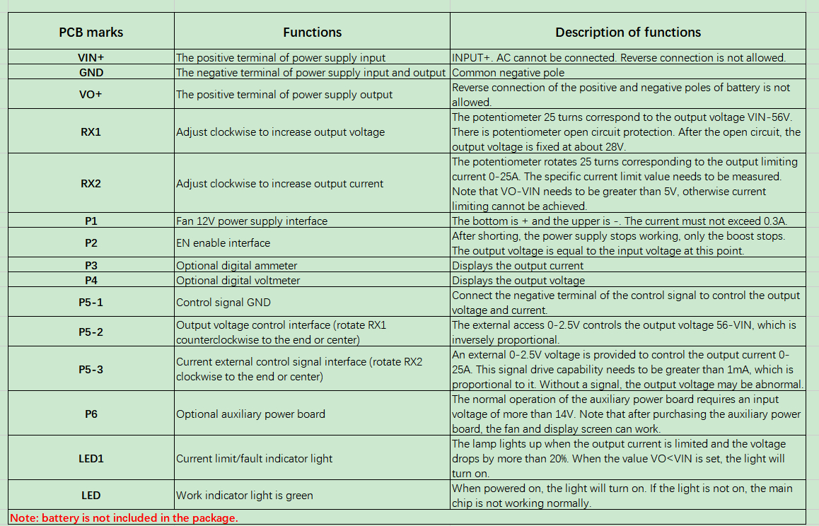
DC Boost Converter Step up Converter Full Set with Fan Display Input 10-48V/40A Output 12-56V
Read before purchasing:
- Do not use a 3A/5A regulated DC power supply as an input to test the power supply.
- Basic technical knowledge and hands-on ability are highly recommended.
- Users need to modify parameters such as undervoltage protection parameters. We can tell you how to modify it.
-
Certain power supply test and measurement capabilities and equipment
are recommended. Do not test this power supply with a 3A adjustable
regulated power supply used in labs.
- Do not test the current-limiting power supply in CC mode of an electronic load.
- When the boost converter is not operating, the input and output are pass-through.
Typical Performance:
- Non-isolated synchronous boost converter
- Wide input DC5-48V, output DC 9-55V
- Peak efficiency> 97.0%
- Over-current protection
- Short circuit and fuse for reverse connection
- Over-temperature protection
- Optional temperature-controlled fan
- Work indicator light
- Adjustable output voltage current
- The output current is externally controllable
- Up to 50A input current
- Battery charge back-charge protection up to 60V
-
Low quiescent current, high regulation accuracy, constant frequency
operation MEI for easy prediction, selectable low EMI spread spectrum
modulation mode
- Power can be over 800W (input > 24V)
- All
tests are made at 24V input voltage, resistive load, and 25°C room
temperature. Parameters are subject to change without notice
Package Included:
- 1 x Set of Boost Converter (power supply board + fan + digital display + heat sink)
Note:
- Battery is not included.
Attention:
1: For inductive or ultra-large capacitive loads, please add a large-capacity LC filter circuit.
2:
Battery can be charged. It is recommended to adjust the output voltage
before connecting the target battery. Charging between the same voltage
level is prohibited.
3: The slow startup time and EN enable can
control the delay time. When the input source start-up time is long, you
need to adjust the output slow startup time. For example, the AC
adaptation output full-load voltage settling time is 50ms, while the
start-up time of this power supply is 2ms, which may cause AC to fail to
start properly with load.
4: The boost power supply cannot completely disconnect the input and output. After the power supply stops working, VO=VIN.
5:
When the output constant voltage and constant current switching is
critical, there will be a deviation of 0.5-1V in the constant voltage
stage. For example, if the current limit is set to 20A at no load of
29.4V, the current will be constant at 20A (-5%) when the output voltage
is less than 28.7V. At 28.8-29.0V, the current may be 18-15A, which is
affected by the internal resistance of the wire and the internal
resistance of the battery. Constant voltage mode is subject to load
regulation.
6: For different applications, some parameters may need to be adjusted.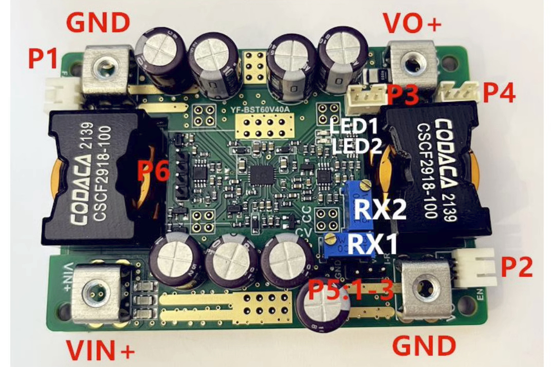
Attention:
1:
When testing this power supply, it must be ensured that the input
source can provide a large enough current (>55A) to ensure that the
power supply does not collapse or even be damaged when it starts at full
load.
2: The input source startup time must be less than the startup
time of this power supply (such as adapter as input), otherwise it may
not be possible to start with load.
3: The input wire connected to
this power supply shall not be too long (the internal resistance of the
wire shall not be too large), otherwise the power supply may cause
oscillation and abnormality.
4: If there is a diode in series with
the input source to this power supply, the power supply may be damaged
by the surge voltage caused by the instantaneous on-off (line BOOST
effect).
5: Do not use the CC mode of an electronic load as the load
of this power supply. It is recommended to use the CR mode. CC mode
absorbs current, this power supply is current limited, and in constant
current mode, this will cause the power supply to crash.
6: It is
recommended to connect the adjustable output voltage to a resistive load
(dummy load) with small current to ensure the real-time adjustment of
the output voltage potentiometer. Otherwise, the output voltage will
change slowly and the regulation will be inaccurate.
7: The current
limit value setting should use resistor's CR mode or battery with
electric quantity less than 60%. For example, if the no-load voltage is
set to 29.4V and then the current limit is set to 20A, the load
resistance will be 0.88Ω~1.17Ω (29.4*0.6/20A<R<29.4*0.8/20A). A 1Ω
resistor is selected and the potentiometer is adjusted until the output
current is 20A.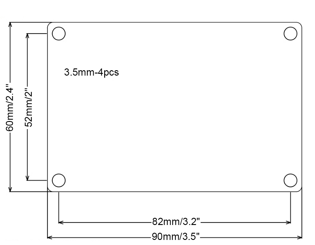
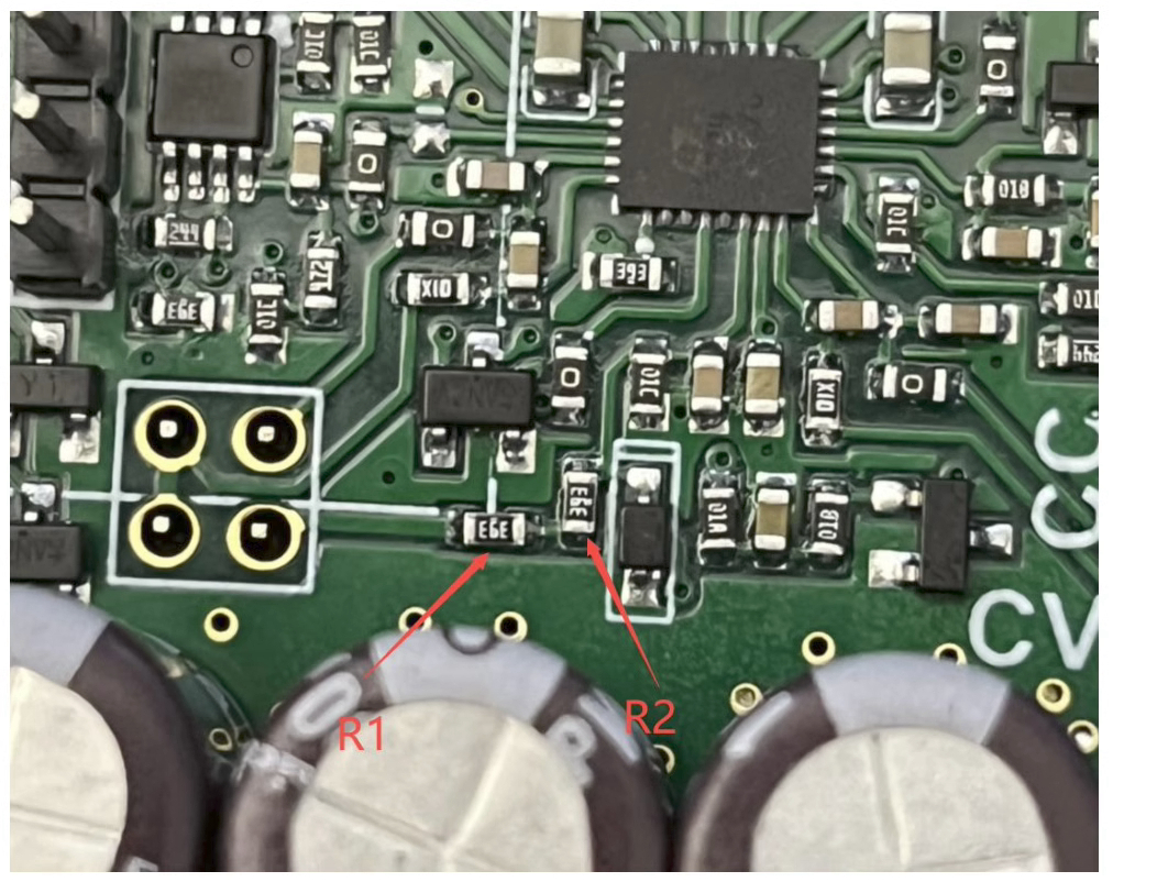
Modify undervoltage protection value:
As
shown in the figure below, the undervoltage value Vin={(R1+R2) /10K+1}
*1.2V. For example, the default value V={(39K+39K)/10K+1}*1.2V=10.56V,
the hysteresis is about 0.5V, and the longer the input wire, the larger
the input current, the greater the hysteresis. Try to stay away from the
undervoltage point to avoid oscillation.