| Quantity | 3+ units | 10+ units | 30+ units | 50+ units | More |
|---|---|---|---|---|---|
| Price /Unit | $7.25 | $7.10 | $6.88 | $6.59 | Contact US |
 RT-Thread RA8P1 Titan Board Dual Core 256GOPS High Performance AI-Accelerated MCU Development Board with Camera Module
$101.26
RT-Thread RA8P1 Titan Board Dual Core 256GOPS High Performance AI-Accelerated MCU Development Board with Camera Module
$101.26
 RT-Thread RA8P1 Titan Board Dual Core 256GOPS High Performance AI-Accelerated MCU Development Board
$94.68
RT-Thread RA8P1 Titan Board Dual Core 256GOPS High Performance AI-Accelerated MCU Development Board
$94.68
 XIAO ESP32-S3 & Wio-SX1262 Kit Micro-controller Development Board Support WiFi/Bluetooth/LoRa for Meshtastic
$16.47
XIAO ESP32-S3 & Wio-SX1262 Kit Micro-controller Development Board Support WiFi/Bluetooth/LoRa for Meshtastic
$16.47
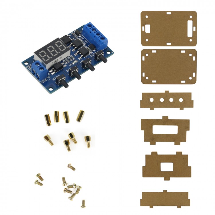
Delay Switch Circuit w/ Shell Trigger Cycle Timing MOS Pulse Generator Replacement For Relay Module
Features:
- Continuously adjustable from 0.1 second (minimum) to 999 minutes (maximum)
- Easy to use and powerful
- Fast and frequent circuit switching at high frequencies and unlimited switching times
- Longer service life than that of common electromagnetic relays
- Dual MOS parallel active output, lower internal resistance, larger current, strong power, 15A, 400W. At room temperature, it meets the requirements of most equipment
- Used to control motors, bulbs, LED strips, DC motors, miniature water pumps, solenoid valves, etc. With this module, you can easily control these devices, which is very convenient.
Highlights:
- Wide voltage operation (5 ~ 36V. Can be used for most equipment
- The interface is clear and simple, powerful, and easy to understand, which can meet your needs
- With emergency stop function (STOP key), with reverse connection protection
- Sleep mode. After enabling, no operation within 5 minutes, it will automatically turn off the display; any key to wake up
- OP, CL, LOP parameters can be set. These parameters are independent and can saved separately
- All setting parameters will be saved after power off automatically.
Working Modes:
- P1: After signal is triggered, the relay turns on OP time and then turns off. During the OP time, please operate as follows
P1.1: Signal triggers again and is invalid.
P1.2: Signal triggers again and retime.
P1.3: Signal triggers again to reset, the relay is power-off, and timing stops.
- P-2: Give trigger signal and after the relay turns off CL time, the relay turns on OP time. After timing is completed, the relay is turned off.
- P3.1: Give trigger signal and after the relay turns on OP time, the relay turns off CL time. Then cycle the above actions, give signal again in the cycle, the relay is power off and stops timing. The number of cycles (LOP) can be set.
- P3.2: No trigger signal is required after power on. The relay turns on OP time and the relay turns off CL time. Cycle the above actions. The number of cycles (LOP) can be set.
- P-4: Signal holding function. If there is a trigger signal, timing is cleared and the relay remains on. When signal disappears, the relay is power off after timing OP. During timing, there is a signal and timing is cleared.
Specifications:
- Working voltage: DC 5V-36V
- Trigger signal source: high-level trigger (DC 3.0V-24V) signal ground and system ground are not shared to improve the anti-interference ability of the system (you can also short-circuit the common ground by yourself)
- Output capacity: DC 5V-36V, continuous current 15A at normal temperature, power 400W. Under auxiliary cooling conditions, the maximum current can reach 30A.
- Static current: 15mA
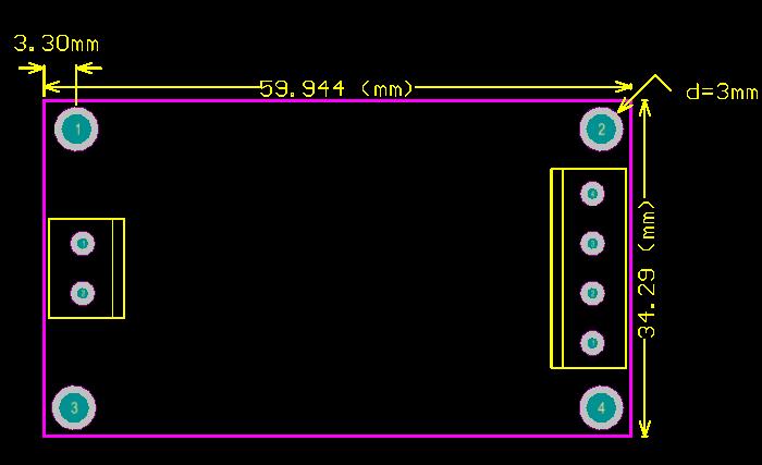
- Service life: unlimited switching; working temperature: -40 to 85℃; Size: 6.0 * 3.4 * 1.2cm
- With optocoupler isolation, enhanced anti-interference ability, industrial-grade circuit board, setting parameters will always be remembered after power off.
Attention:
- The module is an active live output, and the voltage at the output (load) end is equal to the voltage at the input end (DC 5V-36V).
- 'DC +' and load '+' poles are internally short-circuited, but the 'DC-' and load'- 'poles cannot be short-circuited while using. Otherwise the load cannot be controlled to be turned on and off, which is equivalent to the load being always on.
Timing Range:
Continuously adjustable from 0.1 second (minimum) to 999 minutes (maximum)
How to Choose Timing Range:
After setting parameter value in the mode selection interface, short press STOP key to select timing range.
XXX. decimal point is in single digits, timing range: 1 second to 999 seconds
XX.X decimal point is in ten digits, timing range: 0.1 second to 99.9 second
X.X.X. decimal point is all on, timing range: 1 minute ~ 999 minutes
For example, if you want to set OP to 3.2 seconds, then move the decimal point to ten digits, and the digital tube displays 03.2
Parameter Description: OP on time, CL off time, LOP cycle times (1-999 times, "---" means infinite cycles)
These parameters are independent, but they are shared by each mode. For example, on-time OP is set to 5 seconds in P1.1. When users want to switch to P1.2 mode, please enter P1.2 to set the corresponding parameters, OP will be 5 seconds.
Short press SET key on main interface (display 000), OP (CL, LOP) and the corresponding time XXX will be displayed.
If there is only OP (such as mode P1.1, P1.2, P1.3) time in the mode, then short press SET key to display OP and corresponding time.
If there are OP, CL, LOP in the mode (for example, mode P3.1, P3.2), short press SET key to display OP and corresponding time, CL and corresponding time, LOP and corresponding times.
After setting mode, you can easily view the parameters set in the current mode by short pressing SET key on the main interface.
How to Set Parameters:
1. First determine the working mode of the relay.
2.According to the working mode of the relay, in the main interface (when the module is powered on, it will flash the current working mode (default P1.1 mode), and then enter the main interface,) long press SET button for 2s and release it to enter mode selection interface. Press UP and DOWN buttons to select the mode to be set (P1.1 ~ P-4).
3.After selecting the mode to be set (for example, P3.2), press SET button shortly to set the corresponding parameters. At this time, the parameters to be set will flash (OP on time, CL off time, LOP cycle times ("---" means infinite loops). Adjust parameter value through UP and DOWN, support long press (quickly increase or decrease) and short press (increase or decrease by 1 unit). After setting parameter values, press STOP key to select decimal point position and select timing range (corresponding time is 0.1 seconds to 999 minutes). Short press SET key to set the next parameter of the current mode, the process is the same as above.
4.After setting the parameters of the selected mode, press and hold SET button for 2s and then release, the currently set mode will flash. Then return to the main interface and the parameters are set successfully.
Main Interface: "000" is displayed when the relay is not working (no decimal point). The relay has a decimal point in the working state, which is very clear.
Mode Selection Interface: Press and hold SET button to enter. After the setting is completed, long press SET key to exit and return to the main interface, which is very simple.
STOP Button Function Expansion:
Relay Enable Mode:
1. ON: The relay is allowed to conduct during OP ON time.
2. OFF: The relay is prohibited from conducting and is always off.
Short press STOP button on the main interface to switch between ON and OFF. The current state will flash and then return to the main interface. (This function is an emergency stop function. The replay can be on/off with one button.)
Sleep Mode:
1. C-P Sleep Mode: Within five minutes without any operation, the digital tube automatically turns off and the program runs normally.
2. O-d Normal Mode: Digital tube is always on.
Press and hold STOP button for 2s and release it to switch between C-P and O-d states. The current state will flash and then return to the main interface.
Package Included:
- 1 x Delay Switch Circuit with Shell