| Quantity | 3+ units | 10+ units | 30+ units | 50+ units | More |
|---|---|---|---|---|---|
| Price /Unit | $28.54 | $27.96 | $27.08 | $25.92 | Contact US |
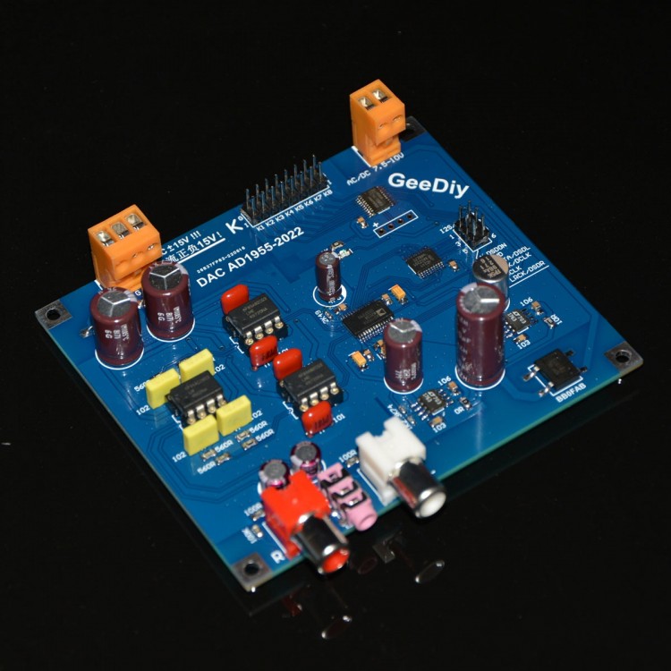
GeeDiy AD1955 DAC Board Audio Decoder Board I2S/DSD Input 24Bit 192K DSD64 DSD128 (Standard Version)
Description:
The AD1955 DAC decoder supports I2S and DSD inputs. PCM mode supports 24bit 192K; it supports I2S, left-aligned, and right-aligned formats! DSD mode supports DSD64 and DSD128.
Optional Version:
- Standard Version: op amps NJM2068D*2 + NJM4556AD*1
- Upgraded Version: op amps LME49720NA*2 + LM4562NA*1
The board controls the AD1955 chip via microcontroller software. The board configuration is done through the K-port.
Set sample rate via K1 and K2: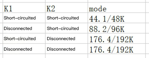
Set data format via K3 and K4: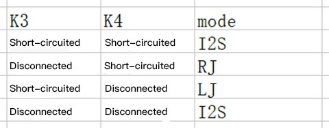
Set the number of bits via K5:
Short-circuit K5 to set PCM to 16bit, and disconnecting K5 to set the PCM to 24bit
Set the MCLK mode via K6:
Short-circuit K6 to set MCLK to 256Fs, and disconnecting K6 to set MCLK to 512Fs
Set the DSD sample rate via K7:
Set the DSD sample rate to DSD64 by short-circuiting K7; Disconnect K7 to set the DSD sample rate to DSD128 (DSD128 mode may be unstable in some cases)
Set PCM and DSD mode via K8:
The DSDON signal of the K8 and the I2S interface are controlled to switch PCM/DSD mode. Since the K8 and DSDON signals are connected to the same pin of the MCU, please disconnect the DSDON (the DSDON pin is suspended) when using the K8 control mode; disconnect K8 when using DSDON control mode. When using K8, short-circuiting K8 is in PCM mode and disconnecting K8 is DSD mode. When using DSDON, the DSDON inputs low level and it is in PCM mode, and when DSDON inputs high level, it is in DSD mode!
Definition of I2S Interface:
1 DSDON ; 2 GND ; 3 DATA ; 4 BCK; 5 MCLK ; 6 LRCK
Electrical Characteristics:
- PCB size: 9.99 x 8.64cm/3.9 x 3.4"
- Screw hole center distance: 9.349 x 7.995cm/3.7 x 3.1" (LxW)
Supply Voltage:
- The analog circuit part supports DC±15V input (please note that mis-connection to AC or wrong line sequence can cause permanent damage to the circuit). The power supply part of the DAC chip supports AC/DC7.5-10V!
- Since some of the analog power supplies of this board are dual DC inputs, a rectified filtered regulated power supply is required!
Package Included:
- 1 x Decoder Board
")
")
")


")


