| Quantity | 3+ units | 10+ units | 30+ units | 50+ units | More |
|---|---|---|---|---|---|
| Price /Unit | $41.63 | $40.78 | $39.51 | $37.81 | Contact US |
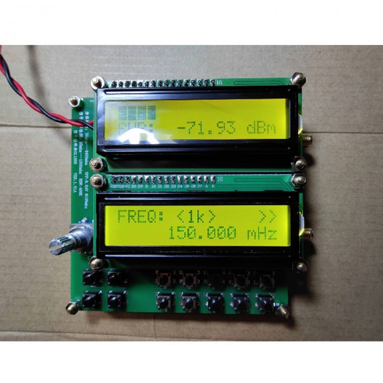
GL1500 RF Power Meter Measuring Range 35MHz-1500MHz RF Signal Power Meter With PPT Buttons
Introduction:
- RF Signal power meter GL1500
- MCU model: ATMEGA8A
- Microcontroller Compiler: CVAVR2.50
- Main RF components: ADF4351, IAM81008, AD8307
Specifications:
- Power supply voltage: DC 4.5V-5.5V. Note that it does not have a built-in voltage regulator unit, so be sure not to supply power over the voltage range. You can use a power bank's 4.96v to power it
- Use current: <200mA
- Input impedance: 50 ohm
- Measurable frequency range: 35mHz-1500mHz
- Measurable power range: -50dBm(W) to +5dBm(W) (absolute value of test power)
- Transferable band pass filter: 400kHz (narrow band)
- The circuit structure of this machine: A transferable 400k bandwidth bandpass filter is composed of ADF4351vfo source and mixing structure and a power meter composed of AD8307
Attention:
The measurement of a general instrument usually refers to the measurement within a certain bandwidth (filtering out unused frequencies by limiting the bandwidth), the so-called narrowband measurement. The purpose of this product is to measure the power of a certain signal.
Package Included:
- 1 x RF Power Meter
Operation:
- The operating keyboard of this product is composed of 14 ppt keys. 10 numeric keys 0-9. ++ and - keys to adjust frequency, and also produce emission output behavior. Short press ++ or - key and output original frequency add 1khz or subtract 1khz. Press and hold the ++ or - button for more than 1 second, and the scanning mode of continuous addition or continuous subtraction will appear. When 35mhz~138mhz, the step is 1khz; when 138mhz~550mhz, the step is 10khz; 550mhz~4000mhz The hour step is 100khz. To end the scan, just press the ++, - button or OK button. The OK button is the output control key. Press it once to transmit, and press it again to stop transmitting. The transmitting caused by ++ or - needs to press the OK button twice to end transmitting. When this product has output transmission behavior, >> will appear in the upper right corner of the display, and C button will stop the transmission and return the frequency to zero.
- The step key is replaced by a down-press mechanical rotary encoder, which is used for continuous addition and continuous subtraction scanning mode for easy adjustment. Cycle selection steps 1K, 10K, 100K, 1M, inherit all key operations of V1.02 version. Rotary encoder arrangement, counterclockwise rotation to decrease, clockwise rotation to increase. Press down to replace the original keyboard <> step selection key.
Attention:
- The EEPROM of this product will record the output frequency displayed when the OK button is pressed the last time. And when the power is turned on again, it will directly transmit the output frequency recorded by the EEPROM by default.
- First set the frequency of the signal source to be the same as the frequency of the measured signal through the keyboard and knob, and then turn the stepping knob left and right until the power meter shows the maximum value, which is the power value of the measured signal.