| Quantity | 3+ units | 10+ units | 30+ units | 50+ units | More |
|---|---|---|---|---|---|
| Price /Unit | $18.78 | $18.39 | $17.82 | $17.05 | Contact US |
 0-10V/0-25mA 4-Channel Current Voltage Signal Generator Brightness Adjustable LED Signal Collector with 35MM DIN-Rail Base
$20.52
0-10V/0-25mA 4-Channel Current Voltage Signal Generator Brightness Adjustable LED Signal Collector with 35MM DIN-Rail Base
$20.52
 0-10V/0-25mA 4-Channel Current Voltage Signal Generator Module Brightness Adjustable LED Signal Collector
$18.57
0-10V/0-25mA 4-Channel Current Voltage Signal Generator Module Brightness Adjustable LED Signal Collector
$18.57
 Automobile Crank Shaft Synchronization Signal Simulator Module 6-Channel Output Signal Generator Module with LED Display
$64.45
Automobile Crank Shaft Synchronization Signal Simulator Module 6-Channel Output Signal Generator Module with LED Display
$64.45
IV Conversion Amplifier Voltage Signal Amplifier Photoelectric Amplifier Module Current To Voltage
Attention:
(1) The interface of our module is clear, featuring stable performance. Please refer to the information provided by our store to do functional verification corresponding to experimental conditions.
(2) The basic parameters of the module are mentioned below. Module PDF file is provided, while engineering files are not provided. If you has operational problems, please consult customer service.
(3) Before using the module, please read the information of this module, understand the power supply and usage restrictions, and avoid damage to the module due to improper operation.
(4) Our store modules guarantee to provide real module parameters, functions and pictures. All modules have passed inspection before shipment.
Description:
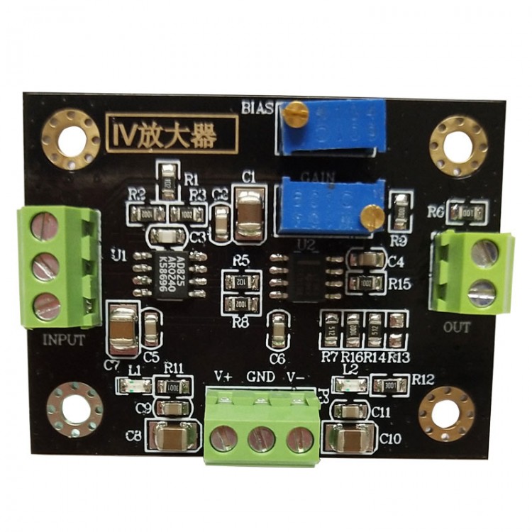
The IV conversion amplifier is a classic IV conversion circuit with a T-type feedback network. It is usually used in photoelectric conversion and some weak current detection places. The minimum current resolution of the module is 10nA, the analog bandwidth is 100K, and it is compatible with most photodiodes. It uses JFET type AD825 chip as its front-end chip. JFET type operational amplifier generally has extremely high impedance and low bias current characteristics, such as ADA4530-1 and other chips. AD825 is cost-effective, and boasts a very low bias current of 20pA and an input impedance of 5*10^11.
Module Parameters:
- Module model: IV conversion amplifier
- Module type: current to voltage amplifier
- Module power supply voltage: ±5V-15V
- Module power supply current: ±30mA
- Input signal form: single-ended current
- Input current range: max. 500uA (Linear within 100uA. It may not be linear if it exceeds 100uA)
- Minimum resolution of input current: 10nA
- Input frequency range: DC-100KHz (increasing frequency will decrease gain)
- Input impedance: high impedance (greater than 10^7Ω)
- Output voltage range: max. 20Vpp (The output voltage is within the power supply)
- Output current: max. ±20mA
- Module gain range: max. 120000*100
- Bias voltage adjustment range: ±4.5V (the higher the power supply, the greater the adjustable range)
- Module protection: none (no reverse connection protection, unlimited current protection)
- Module weight: 16g/0.04 lb
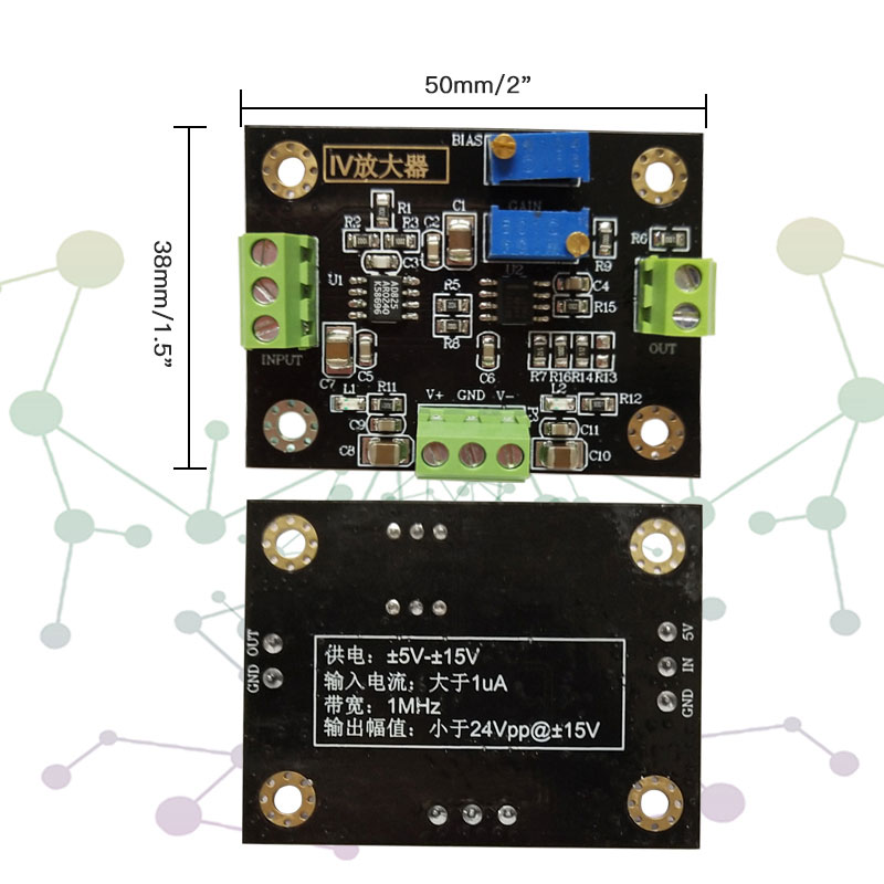
- PCB size: 50 x 50 x 7mm/2 x 2 x 0.3" (LxWxH)
- Module heating: no heat sink (no heat dissipation required for normal operation)
- Module heating factor: excessive power supply voltage damages the chip or the module is damaged
- Module working temperature: -25℃ to 75℃ (industrial grade)
- Module features: output positive and negative power LED indication
- Application range: photoelectric detector, data acquisition front end, weak signal detection, etc.
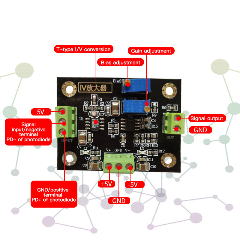
- Power supply interface type: 3.81-3P terminal block
- Signal interface type: input 3.81-2P terminal block; output 3.81-2P terminal block
Package Included:
- 1 x IV Conversion Amplifier
Precautions:
(1) The power supply of the module is a positive and negative dual power supply, and the voltage cannot exceed ±15V.
(2) Since the module is a high-precision device, in order to avoid unnecessary interference, it is recommended to use a linear power supply.
(3) For the output signal, it is recommended to use a good wire for input and output signals to ensure a good grounding. You can use an oscilloscope or a voltmeter to observe the effect. Poor contact or poor quality cables may cause signal attenuation or excessive noise.
FAQ:
Q1: The module outputs DC voltage as soon as it is powered on, and the input is not connected. How to adjust?
A1: First, you need to determine whether the module is powered by a positive and negative dual power supply. Secondly, adjust the bias potentiometer, adjust the output to close to 0, and then connect to a photocell or input current. When there is current input or the photodiode has photo-current generated, the output voltage will change. If the output voltage does not change, it may be that the magnification is too small. You can turn the potentiometer clockwise to increase the magnification.
Q2: What is the adjustable range of the module offset?
A2: Currently, the adjustable range of the module's offset is ±4.5V. Increasing the power supply can increase the adjustment range of the output voltage and bias voltage.
Q3: When there is light, the output signal is always 4V. What is the problem with no change in light intensity?
A3: When the input current is 0~100uA, the output signal is linear. If it exceeds this range, the output signal will be saturated. If the intensity of light does not cause changes, and the presence or absence of light changes, most of the input photo-current is too large. This is related to its gain adjustment. The first-stage trans-impedance amplification of the module is fixed at 120k. The second-level sliding change is adjustable up to 100 times. The maximum of two levels is 12 million times. If the first stage is distorted and the later stage is adjusted to 1 times, it will also be distorted.