YDMT42B Micro Pulse Type 42/35/28/20 Stepper Motor Driver Module 12-32V with 42 Stepper Motor
Couldn't load pickup availability

42 Stepper Motor Parameter:
- Size: 42 x 42 x 40mm
- Current: 1.7A
- Torque: 0.4N.m
- Net weight: 285g
Description:
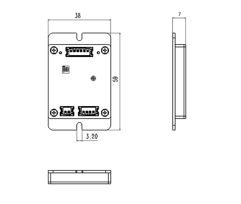
- YDMT42B stepper motor driver is specially designed for high-precision control scenarios such as medical equipment, biopharmaceuticals, scientific research instruments, industrial automation, 3D printing, CNC machine tools, security equipment, etc. The product adopts a compact structure (size of 59x38x7mm), integrates multiple intelligent protection and flexible control functions, supports 12V-32v wide voltage input, adapts to multiple motor types, and can achieve continuous adjustment of 0-2.5A current, combining stability and efficiency.
Features:
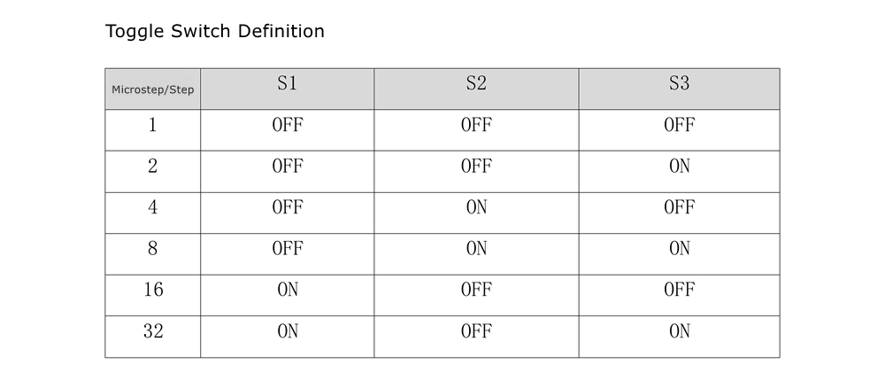
High precision micro step subdivision:
- YDMT42B supports 1/32 micro step subdivision, increasing the number of steps per revolution to 6400 steps (motor step angle of 1.8°), effectively reducing motor vibration and noise, suitable for scenarios that require sub millimeter positioning accuracy (such as 3D printing nozzle control, medical equipment precision movement).
Low voltage and signal compatibility:
- Supply voltage 12V-32V: Suitable for various power supply solutions such as industrial power supplies and lithium batteries, with strong resistance to voltage fluctuations.
- Signal input compatible with 5V-24V: It can be directly connected to controller such as PLC, motion control cards and does not require additional level conversion circuits, simplifying system design.
- Optocoupler isolation: Supports differential signal and single ended signal input, supports common cathode and common anode connection method, optocoupler isolation eliminates interference.
- Pulse input: The pulse response frequency can reach up to 200kHz.
Intelligent current control:
- 0-2.5A infinitely adjustable: The output current is precisely adjusted through a potentiometer to adapt to stepper motors with different torque requirements (such as the 42/35/28/20 series), avoiding motor overheating or insufficient power.
- Adaptive current regulation: Built in current closed-loop control technology, real-time monitoring of load changes and dynamic adjustment of output to improve system energy efficiency.
Multiple security protections:
- Overcurrent protection (OCP): When the output current exceeds the set threshold, the drive signal is automatically cut off to prevent damage to the motor or chip.
- Overheating protection (TSD): Built-in temperature sensor, it triggers a shutdown when the temperature exceeds 85°C and automatically recovers when the temperature drops.
- Undervoltage lockout (UVLO): When the supply voltage is lower than 10V, the driver enters a protective state to avoid abnormal operation.
- Fault indication (nFAULT): When overcurrent/overheat protection occurs, the driver alarm indicator lights up.
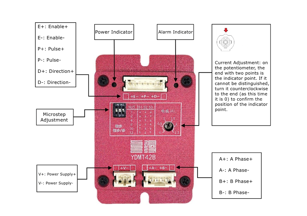
Terminal Definition:
E+: Enable positive, default enable when no signal is connected, disable when conductive; Compatible with 5V-24V.
E-: Enable negative.
P+: Pulse positive; Compatible with 5V-24V, no need for external resistors.
P-: Pulse negative.
D+: Positive direction, compatible with 5V-24V, no need for external resistors.
D-: Negative direction.
V+: Positive power supply, voltage range of 12V-32V.
V-: Negative power supply.
A+: Positive stepper motor phase A.
A-: Negative stepper motor phase A.
B+: Positive stepper motor phase B.
B-: Negative stepper motor phase B.
Indicators:
- Power indicator: light on for normal power supply; light off for power failure.
- Alarm indicator: light on for driver over-current/over-temperature protection; light off for normal operation.
Potentiometer Definition:
- Current Adjustment: Drive current regulation, continuously adjustable from 0-2.5A, on the potentiometer, the end with two points is the indicator point. If it cannot be distinguished, turn it counterclockwise to the end (at this time it is 0) to confirm the position of the indicator point.
Microstep/subdivision calculation:
- To calculate how many pulses Pc the controller needs to send for a stepper motor to complete one revolution, we need to know the step angle θ of the stepper motor (step angle refers to the angle the rotor rotates for each pulse signal received by the stepper motor). Common step angles include 1.8°, 0.9°, 3.6°, and 0.72°. Based on the step angle, we can calculate Pc=360/θ. If the step angle is 1.8°, then the number of pulses required for the motor to rotate once is Pc=360/1.8=200 (without using micro steps or with micro steps being 1).
- Microstep Sm is the number of pulses used to control each step angle when controlling a stepper motor. For example, if the step angle is 1.8° and the microstep is set to 4, it means that 4 pulses are used to control the stepper motor to rotate 1.8°. When using microstep for control, the motor needs to send a pulse count Pc=(360/θ) * Sm per revolution. If the step angle of the motor is 1.8° and the micro step is set to 4, the number of pulses required for the motor to rotate once is Pc=(360/1.8) * 4=800
Package Included:
- 1 x Stepper Motor Driver Module
- 1 x 42 Stepper Motor