| Quantity | 3+ units | 10+ units | 30+ units | 50+ units | More |
|---|---|---|---|---|---|
| Price /Unit | $39.57 | $38.76 | $37.55 | $35.94 | Contact US |
 FUZRR ES3000P Multifunctional Micro-controller 3-Wire Ground Resistance Tester 0-20Kohms High Precision Earth Resistance Tester
$275.47
FUZRR ES3000P Multifunctional Micro-controller 3-Wire Ground Resistance Tester 0-20Kohms High Precision Earth Resistance Tester
$275.47
 150W Multifunctional Bluetooth Battery Capacity Tester CC/CR/CP/CV/PT/BRT Intelligent DC Programmable Electronic Load
$59.21
150W Multifunctional Bluetooth Battery Capacity Tester CC/CR/CP/CV/PT/BRT Intelligent DC Programmable Electronic Load
$59.21
 FUZRR ES3090E 220A Loop Resistance Tester Micro-ohmmeter for High Voltage Switch Contact Resistance Measurement
$1,466.23
FUZRR ES3090E 220A Loop Resistance Tester Micro-ohmmeter for High Voltage Switch Contact Resistance Measurement
$1,466.23
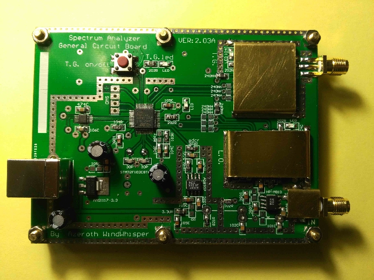
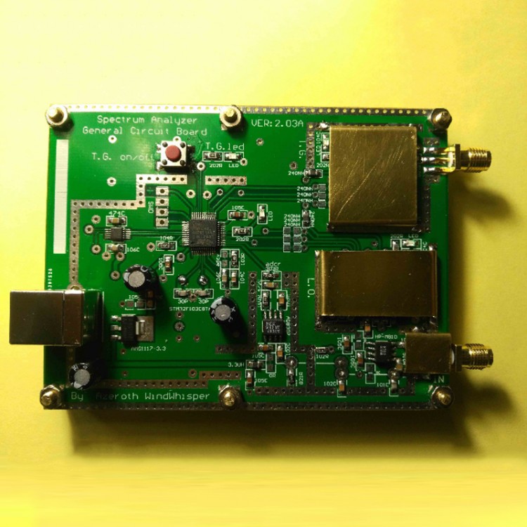
Simple Spectrum Analyzer D6 w/ Tracking Generator T.G. V2.03A Version
Description:
Why do we need a tracking source: the bottom noise of a normal instrument (multi-bandwidth narrowband receiver) can generally reach - 130dBm, with a few watts of white noise source - 50dbm point-frequency noise can achieve the purpose of bandwidth measurement. The bottom noise of this amateur simple spectrum (belonging to broadband receiver) has reached - 60dBm, and the dynamic logarithm ratio of bandwidth measurement needs to reach at least 60dB, so it must be matched. Tracking source, after all, the point frequency of tracking output is above 0 dbm.
Our products are divided into two categories according to their actual uses:
1. The sweeper with DDS as the core and the LC panel are used to measure the high frequency parameters of LC by sweeping line, including the high frequency dielectric loss of capacitor, Q value of inductance and parasitic capacitance, Q value of LC loop, inductance and capacitance, and the medium frequency path with the highest working frequency of tens of mhz.
2. Simple spectrum with T.G. and Bridge Based on PLL is also used to measure S21 (dB) of AC path by sweeping frequency line, and to measure the general situation of S11 (main antenna) of circuit network port by bridge, aiming at the high frequency channel with working frequency over tens of mhz.
For the enthusiasts who like to do things, the frequency sweeper is simple to make, the frequency of the sweeper is very high, it is the working machine, after all, the selection of intermediate frequency materials is very critical.
The relationship between high frequency S parameters and circular graphs is briefly introduced. There are three expressions of S parameters in network transmission, i.e. power ratio (dB) of port input and output, magnitude ratio (Mag) of port incident wave and reflection wave, and phase difference (Ang) of port incident wave and reflection wave. These are basic analysis parameters. Circle diagrams are derived from S parameters. The reflection coefficients and phases of standing wave ratio (VSWR) are obtained. They can be interchanged by manual calculation and software simulation. For example, the S11 parameter is actually the reflection coefficients of input ports, while the standing wave ratio is the reflection coefficients of input ports.Another expression of reflection coefficient.
In a word, all high frequency parameters are functions of frequency and are expressed in the form of geometric curves.Radio frequency instrumentation usually detects the influence of the measured circuit on the amplitude and phase of electromagnetic wave by using the continuous variation of the frequency of electromagnetic wave. This is different from the way that electricians deal with zero-frequency DC or fixed low-frequency only need "point scalar" to understand the working state of the circuit, which can not be simply applied metaphysically.
Specifications:
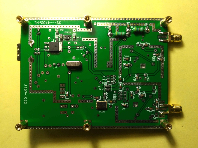
- JTGP-1033Simple Spectrum (with Trace Generator), Simple Signal Source V2.02 Edition
- Attribute: RF Frequency Domain Analysis Tool
- Interface:USB
- Power supply:USB
- Standby Current: <100mA
- Sweep current: <350mA
- Sweep bandwidth:33 mHz - 4400 mHz
- Open Tracking Source Output Bandwidth 33 MHz - 3000MHz
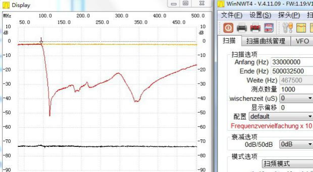
- Sweep stepping: > or33-68.75 mHz/125 Hz, 68.75-137.5 mHz/250 Hz, 137.5-275 mHz/500 Hz, 275-550 mHz/1 kHz, 550-1100mHz/2kHz, 1100-2200mHz/4kHz, 2200-4400mHz/8kHz,
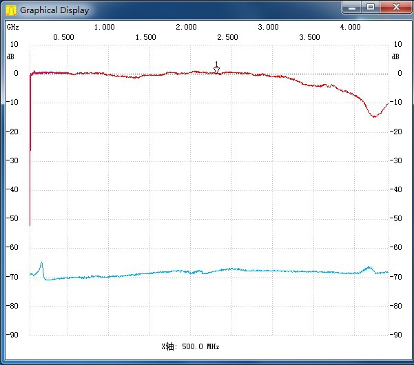
- Sweep Speed: > Frequency Sweep Speed800spot/second
- Sweep Dynamic Logarithmic Ratio: > 50dB
- Point or sweep output power:0 dBm
- Input detection: <10 dBm
- Background:-60dBm
- Computer side software:NWT4.11.09Edition
- Computer operating system: For WinXP,Win732, Win764 (Some of the installations of Win10 can be used and some can't. The reason has not been found yet. It's amazing.)
- Spectrometer is commonly known as radio frequency multimeter.
- Applicable: Radio enthusiasts, young students
Component Introduction:
Core components: STM32F103 single-chip computer, as a result of the built-in can 2.0 controller has become the most familiar single-chip computer for hardware engineers. Hardware is written in C MDK, the official standard language of Hardware Country, which is convenient for communication.
Adf4351, the traditional VCO + PLL + 6 series high-speed bistable circuits (except 2 circuits, D trigger). 35-2200 MHz is obtained by frequency division. After shaping, the fundamental wave amplitude does not change much, which is difficult to achieve in full bandwidth for high frequency DDS. (After the signal is divided into frequencies, it must be rectangular wave, and the amplitude will change to trigger level)
Often playing with VCO, we have the experience that the frequency output varies greatly with the amplitude of the fundamental wave. It is impossible to use the original oscillator directly as the "source" of measurement. The output fundamental wave amplitude must be stabilized as ADF4351 does.
IAM81008, mixer chip RF up to 5 GHz mixer chip, mixer below 50 MHz 8-foot 6-foot series capacitor to GND optimization. LO local oscillator input must be greater than - 5 dbm, in addition, IAM81008 power supply electrode must be strictly stable more than 4.85 v. I use the home-made ps3120 for its power supply.
AD8307, Logarithmic Detector Amplifier, Used for Power Measurement, Key Components.
Ch340g, homemade USB to TTL chip, good driver.Generally, STM32F103 is not driven by usb, which reduces the cost of interruption system of single-chip microprocessor, although the performance of this single-chip microprocessor exceeds the USB of its own. Ch340g performance-price ratio is very high.
In the information age, the mature circuit application principles of these chips can be obtained freely and conveniently on the internet. Radio enthusiasts are encouraged to use their hands and brains to make this simple and simple radio measurement tool, so as to improve their knowledge level and understanding depth.
Working Principle:
Physically, no oscillator will produce only "fundamental wave". There will always be overtone (homogeneous harmonic, even harmonic and inter-wave). It is sometimes difficult to filter overtone directly. After mixing the measured signal with the local oscillator, a lot of combined differential frequencies will be obtained. Among them, the difference frequencies between the fundamental wave of the local oscillator and the measured signal are the lowest and the amplitude is the largest, and the low-pass filter or the low-pass filter is used. The band-pass filter (RBW) only detects the difference frequency and sends it to the logarithmic amplifier at the later stage to get the frequency and amplitude of the measured signal. The key point is that the fundamental wave amplitude of the local oscillator does not change much at different frequencies, overtone is not used, because mixing will be "filtered out" by low pass (RBW).
Similarly, the fundamental frequency difference between the tracking source oscillator and the local oscillator is always 120 khz. We can always observe the amplitude change of the 120 kHz difference frequency. This is the principle of differential frequency scanning.
"Spectrum analyzer" Is used to measure the spectrum distribution of the"signal". It is an instrument to observe the size of the fundamental wave and overtone of the signal. To put it plainly, it is to analyze the waveform displayed by the oscilloscope in frequency domain.
"Sweeper" It is used to analyze the frequency characteristics of the circuit's"AC path". The S21 parameter curve is obtained. Small step is more suitable for measuring the harmonic frequency of LC circuit, calculating capacitance inductance, judging Q value by the depth of harmonic point, observing the high frequency dielectric loss of capacitance by comparison, calculating parasitic capacitance of inductance, and selecting materials for self-design. It is very practical for radio enthusiasts.
"Spectrum with Tracking Source". Not only can we use the bridge measurement network S11, S22 "single port", but also can cooperate with the tracking source to measure the amplitude-frequency characteristics of the AC channel S21, S12 "double port".
Oscilloscope Time Domain Instrument. The waveform displayed reflects the time base. Phase frequency Amplitude frequency Relationship and Frequency of fundamental wave.
Spectrometers, sweepers and oscilloscopes have different emphasis in the field of radio frequency, and can not be replaced by each other. They are all basic instruments, and they are equally important.
The spectrum obtained by "difference frequency scanning" is basically the same as that obtained by FFT calculation of digital oscilloscope, but the former has no more primitive and direct calculation process. The calculation of FFT transformation trigonometric function is bound to be limited by Lagrangian remainder terms. There is a problem of accuracy. As we often say, "3.14" is pi. In fact, Pi is not only an irrational number, but also a transcendental number. There is also no bandwidth-dependent sampling problem. In addition, the differential frequency scanning method is not suitable for detecting WiFi type frequency hopping signal measurement. The detection of frequency hopping signal is a combination of radio frequency frequency frequency meter and radio frequency power meter. This method has low cost and no bad effect. The more advanced time-sampled multi-bandwidth spectrometer (estimated to be very expensive) is used.
Note: There is a single-key switch on the board to control the output of the tracking source. By default,T.G. Tracking function closed state,As a signal source, the state remains unchanged. After all, playing radio means "filtering" and "bandwidth".The parameters of S21 and S12 in the measurement network must have tracking source, and the parameters of S11 and S22 in the measurement network with radio frequency bridge must also have tracking source. In a word, the parameters of S22 must have tracking source.It's necessary to have a tracking sourceSince the input and detection end of the machine can bear up to 10 MW or 10 dbm, it is better to use the tracing source inside the machine and try not to connect it outside.When the noise source replaces the tracking source, the total output power of the full-band noise source is too large, such as the 1 kHz bandwidth of the noise source.Output 0.001 mW is - 30 dbmW.Then the total theoretical output of 100 MHz bandwidth should be 100 W at the same time.
Appearance: The size of the circuit board is 75mm X99mm. This is a new design. It optimizes and simplifies the circuit (taking into account the requirements of the enthusiasts for copper clad plate etching), cancels the shielding cover, and rationally simplifies the manufacturing process. If the background of some machines is lower, the shielding cover should be added to the oscillator. The background is directly determined by the straightening structure of the mixer.
Package Included:
- 1 x Simple Spectrum Analyzer
- 2 x SMA Jumper Wires (20cm Long)
- 1 x USB Cable