| Quantity | 3+ units | 10+ units | 30+ units | 50+ units | More |
|---|---|---|---|---|---|
| Price /Unit | $0.00 | $0.00 | $0.00 | $0.00 | Contact US |
 Gravity Waves BLACK DOMAIN Tube Amp Attenuator Dummy Load Box for Tube Amplifiers ≤200W
$143.04
Gravity Waves BLACK DOMAIN Tube Amp Attenuator Dummy Load Box for Tube Amplifiers ≤200W
$143.04
 Gravity Waves Tube Amp Bunker Tube Guitar Amp Attenuator Load Box and Cab Sim Combo (Silver)
$414.91
Gravity Waves Tube Amp Bunker Tube Guitar Amp Attenuator Load Box and Cab Sim Combo (Silver)
$414.91
 20W Gravity Waves Bluespace White All-Tube Guitar Amplifier Guitar Tube Amp Combo with Stand & Pedal
$1,490.66
20W Gravity Waves Bluespace White All-Tube Guitar Amplifier Guitar Tube Amp Combo with Stand & Pedal
$1,490.66
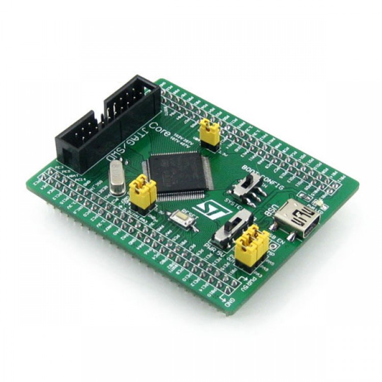
STM32F407VET6 Cortex-M4 Core Board Development Board Minimum System Board
Introduction
- Core407V is a based STM32F407VET6 as the main chip core board , its most important feature:
- The basic circuit board MCU , including the oscillator circuit , USB power management circuitry , USB interface
- Leads to all I / O resources
- With JTAG / SWD debug download interface
- Pin spacing of 2.54mm, smaller, suitable access to the user's system
Chip Introduction
- STM32F407VET6
- Kernel : Cortex-M4 32-bit RISC;
- Features: single-cycle DSP instructions ;
- Operating frequency : 168MHz, 210 DMIPS/1.25 DMIPS / MHz;
- Operating voltage : 1.8V-3.6V;
- Package : LQFP100;
- Storage resources : 512kB Flash, 192 +4 kB SRAM;
- Resource : 3 x SPI, 3 x USART, 2 x UART, 2 x I2S, 3 x I2C;
- 1 x FSMC, 1 x SDIO, 2 x CAN;
- 1 x USB 2.0 FS / HS controller ( with dedicated DMA);
- 1 x USB HS ULPI; ( for external USB HS PHY)
- 1 x 10/100 Ethernet MAC;
- 1 x 8 to 12-bit parallel camera interface;
- 3 x AD (12, 1us, timesharing 24 ), 2 x DA (12 -bit) ;
- Debugging Download : Supports JTAG / SWD interface debugging download and support IAP.
- AMS1117-3.3 (PCB backside )
- 3.3V regulator device .
- MIC2075 (PCB backside )
- USB power management devices .
Other Devices Profile
- \"5Vin\" or \"USB\" power selector switch
- Switch to the top, select USB powered ;
- Switch to the next , select 5Vin supply.
- BOOT state setting switch
- You can set the status BOOT0 . (BOOT1 rarely need to be used, by supporting cable modify its state )
- Power LED
- Reset button
- 8M crystal
- 32.768K crystal (PCB backside )
- Use of available built-in RTC , or for the calibration.
Interface Overview
- JTAG / SWD interface,
- Support download and debug .
- USB interface
- USB communication with PC .
- MCU pin interface ( with VCC / GND)
- Leads to VCC.GND and all I / O, convenience and peripherals carry on connection.
- 5Vin input interface
- When the USB as the HOST / OTG O'clock , need to enter the 5V power supply.
Jumper / Switch Description
- USB Jumper
- Short jumper : When using a USB jump .
- Disconnect Jumper: does not affect the I / O.
- VBAT select jumper
- Short jumper : The system power supply ;
- Disconnect Jumper : You can VBAT access to an external power source , such as batteries .
- VREF select jumper
- Shorting jumper : VREF + / VREF- access VCC / GND;
- Disconnect Jumper: can be customized VREF + / VREF-.