| Quantity | 3+ units | 10+ units | 30+ units | 50+ units | More |
|---|---|---|---|---|---|
| Price /Unit | $153.31 | $150.18 | $145.49 | $139.23 | Contact US |
 Black 3D-Printed Mini ESP32 Marauder Development Board Positioning Module with 1.44-inch Screen
$33.36
Black 3D-Printed Mini ESP32 Marauder Development Board Positioning Module with 1.44-inch Screen
$33.36
 White 3D-Printed Mini ESP32 Marauder Development Board Positioning Module with 1.44-inch Screen
$33.36
White 3D-Printed Mini ESP32 Marauder Development Board Positioning Module with 1.44-inch Screen
$33.36
 Black Shell T-Embed-CC1101 Plus ESP32-S3 Development Board NRF24L01 2.4GHz ISM Transceiver with 1.9-inch LCD
$88.55
Black Shell T-Embed-CC1101 Plus ESP32-S3 Development Board NRF24L01 2.4GHz ISM Transceiver with 1.9-inch LCD
$88.55
Three-phase Four-leg Sine Wave IGBT Module Driver Board V6.0 Inverter Control Board RS485 Communication
Description:
- The development of inverter control technology is rapid, but with the increase of load types, it is easy to encounter three-phase load imbalance. At this time, the output three-phase voltage is difficult to achieve balance, which will to some extent affect the normal use of the load.
- In order to solve the problem of unbalanced load affecting power quality, a three-phase four-leg inverter is adopted on the basis of a traditional three bridge arm inverter. This inverter can effectively suppress the voltage disturbance caused by three-phase unbalanced load current under unbalanced load conditions, ensuring that the output three-phase voltage is approximately symmetrical.
- Board size: 185 x 95mm
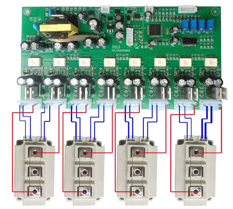
Each phase of the three-phase four-leg and the fourth leg form a full bridge inverter. The input filtering capacitance required for a three-phase four-leg inverter of the same power level is much smaller than that of a three-phase half bridge inverter. Therefore, compared with the three-phase half bridge inverter, the three-phase four-leg full bridge inverter has the advantages of small size, light weight, and low cost, and therefore has good application value. This product is a zero sequence current injection PWM control that can achieve decoupling control of three-phase four-leg inverters, and the control method is simple, easy to understand and implement. Compared with conventional sine wave modulation methods, the utilization rate of DC bus voltage has been improved, and it has good ability to handle unbalanced loads.
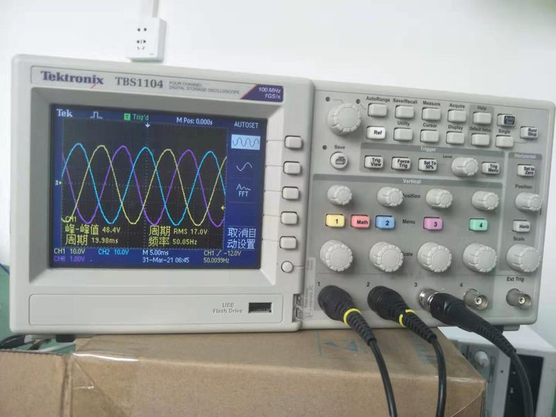
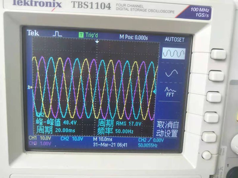
- Three phase four leg inverters are mainly used for UPS, intermediate frequency converters, and aircraft mounted variable speed constant frequency power generation systems that supply power to three-phase asymmetric loads. Three phase four leg inverter with SPWM wave frequency of 16.000KHz. Each phase of the circuit is independently controlled and there is no coupling relationship between them. It is possible to decompose the three-phase four-leg inverter into three independent single-phase full bridge inverters, with each inverter's output voltage phase differing by 120° from each other.
A typical three-phase inverter is a three-phase half bridge inverter with only three bridge arms. When supplying power to asymmetric loads, an output transformer must be connected to the output terminal or a neutral point must be connected to form a transformer. NFT is an auto-transformer with a 1:1 ratio. Although it has a smaller volume and weight than the output transformer, its volume and weight vary with the degree of load asymmetry. The greater the asymmetry, the greater its volume and weight. In order to eliminate the output transformer and reduce the volume and weight of the inverter, a bridge arm can be added to the three-phase half bridge inverter to form a neutral point N, thus forming a three-phase four leg inverter that adapts to asymmetric load output.
The structure of a three-phase four leg inverter can have balanced or unbalanced three-phase loads, linear or nonlinear. Due to the addition of the fourth bridge arm, the control has become very complex.
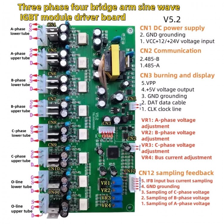
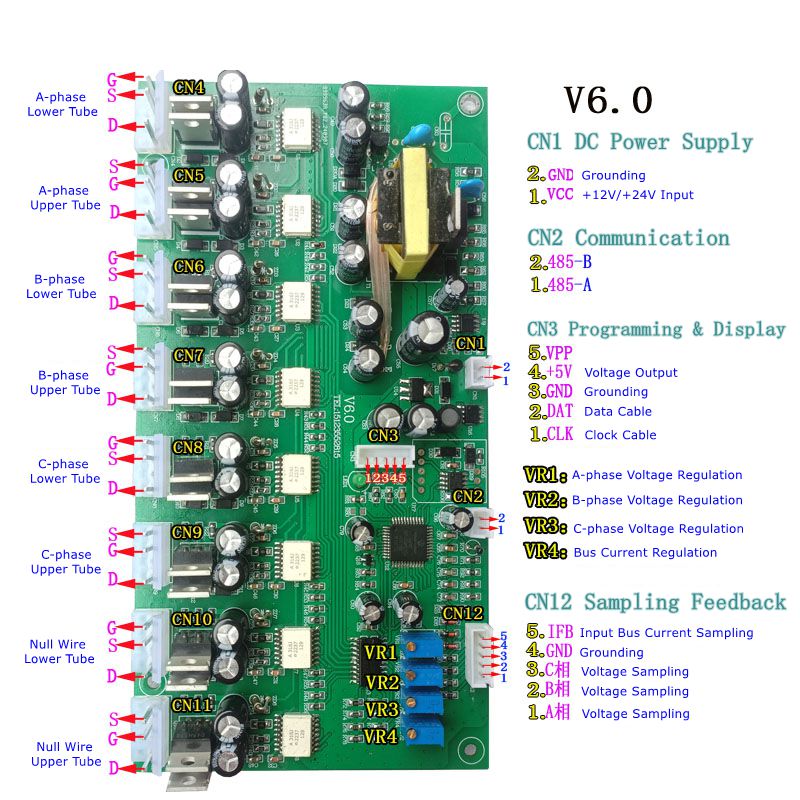
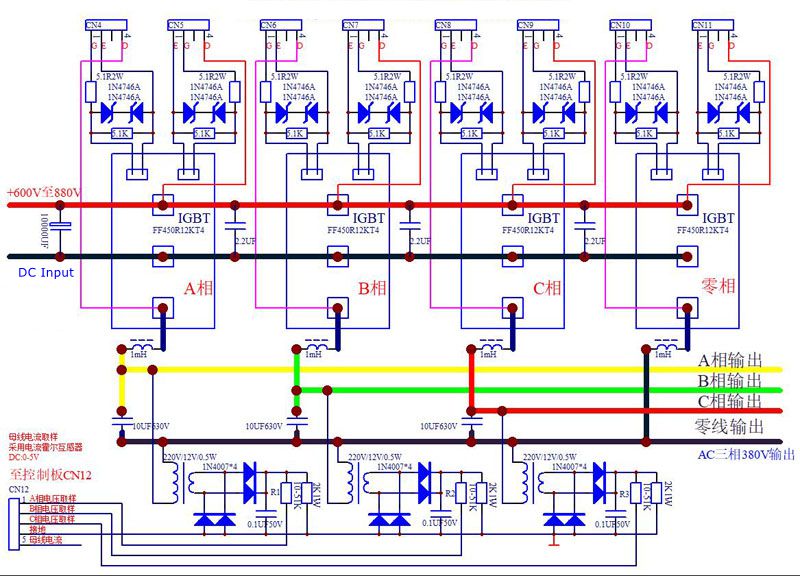
- The switching mode of a three-phase four leg inverter is composed of a three-phase half bridge inverter and a common bridge arm composed of CN10 and CN11.
- Switches CN4 and CN5, along with CN10 and CN11, form an A-phase full bridge inverter;
- Switches CN6 and CN7, along with CN10 and CN11, form a B-phase full bridge inverter;
- Switches CN8 and CN9, along with CN10 and CN11, form a C-phase full bridge inverter;
- The neutral point is formed by the shared bridge arms CN10 and CN11. Due to the shared bridge arms of CN10 and CN11, the excitation of the three-phase output currents of A, B, and C is mutually constrained, which is a difficult control point for the three-phase four leg inverter.
The traditional three-phase three-leg inverter outputs three-phase three wire, with only line voltage and no neutral or phase voltage. It can only obtain phase voltage and null line by connecting the output to a three-phase isolation transformer. Transformers of the same power are bulky.
If the null line is obtained from the midpoint of the DC bus capacitor, it is a three-phase half bridge inverter that can generate three-phase four wire outputs with both phase and line voltages. The output phase current is small, and the input capacitor capacity needs to be large, causing the midpoint voltage to drift easily.
Three phase four leg outputs three-phase four wire, with both line voltage and phase voltage and null line; The null line can output high power and can withstand unbalanced loads in three phases.
Key Features:
- Pure high-frequency inverter conversion circuit.
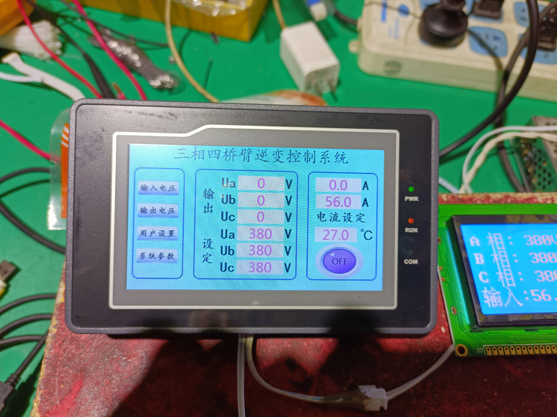
- Local mode/485 communication mode automatically switches, 485 communication takes priority.
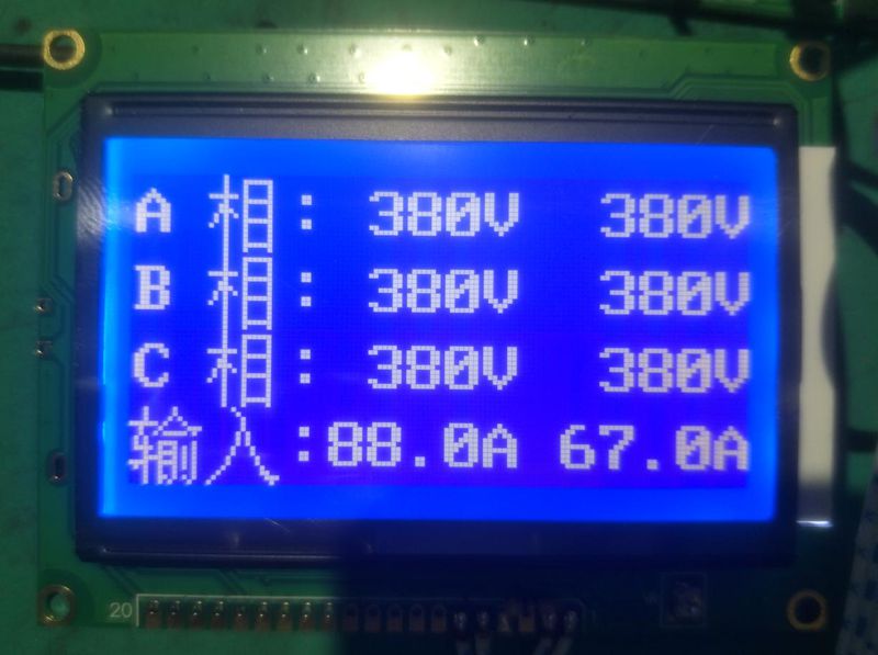
- The output voltage, current, and power can all start from 0, be constant and adjustable, and operate on a 485 touch screen.
- It has a constant output voltage and a constant bus current, which is completely comparable to the power frequency machine when starting inductive loads.
- Power on can achieve soft start output. When the bus is in constant current output mode, the output waveform remains pure sine wave.
- Without using 485 communication, this control board can set the output voltage and current.
- Support external 485 communication voltage, current display and setting.
- This board comes with power on/off control output function, default power on.
- R105 and R106 are swapped, and this control board is powered on and in the off state, requiring 485 communication to turn on the device.
- Default startup time of 5 seconds, dead zone of 2uS, without output undervoltage/overvoltage protection, convenient for beginners to install and use
Package Included:
- 1 x Control Board