| Quantity | 3+ units | 10+ units | 30+ units | 50+ units | More |
|---|---|---|---|---|---|
| Price /Unit | $48.39 | $47.40 | $45.92 | $43.95 | Contact US |
 Gravity Waves BLACK DOMAIN Tube Amp Attenuator Dummy Load Box for Tube Amplifiers ≤200W
$143.04
Gravity Waves BLACK DOMAIN Tube Amp Attenuator Dummy Load Box for Tube Amplifiers ≤200W
$143.04
 Gravity Waves Tube Amp Bunker Tube Guitar Amp Attenuator Load Box and Cab Sim Combo (Silver)
$414.91
Gravity Waves Tube Amp Bunker Tube Guitar Amp Attenuator Load Box and Cab Sim Combo (Silver)
$414.91
 20W Gravity Waves Bluespace White All-Tube Guitar Amplifier Guitar Tube Amp Combo with Stand & Pedal
$1,490.66
20W Gravity Waves Bluespace White All-Tube Guitar Amplifier Guitar Tube Amp Combo with Stand & Pedal
$1,490.66
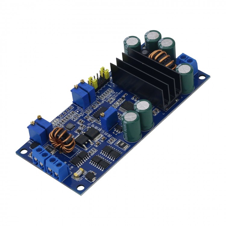
UPS-1228-12 DC UPS Power Module Uninterruptible Power System for PC/Access Control/Security/Industrial Control
Description:
- UPS-1228-12 is a high-efficiency DC UPS power module designed specifically for applications that require DC backup power. The module has a wide input voltage range and supports lead-acid batteries, lithium-ion batteries, lithium-polymer batteries, and lithium iron phosphate batteries as backup batteries. It has complete charging management functions and the onboard automatic voltage regulation circuit to directly provide regulated DC power to the device. When switching between the input power supply and the battery, the output voltage remains stable and the load operation is not affected in any way.
- When the input power supply has electricity, the module charges the battery and outputs the stabilized power supply to the device. When the input power is cut off, the module automatically switches to battery power supply mode and provides stabilized power to the device. The switching time is zero and does not affect the load operation. The onboard MCU will monitor the battery voltage in real time when powered by battery. When the battery discharges to the set undervoltage threshold voltage, the power automatically turns off the output and enters a low-power sleep mode. The power supply can only be started when the input is re-powered on or the battery voltage is restored to the starting threshold voltage.
- Please note that the charging part of this module is step-down charging, and the input power supply voltage must be 1V higher than the charging cutoff voltage of the battery it charged in order to provide power supply. For example, if the battery uses a 12V lead-acid battery with a charging cutoff voltage of 13.8V, then the input power should be a DC power between 14.8V and 28V. So we can choose a common 19V or 24V power adapter as the input power supply.
- The module comes with an automatic voltage regulator circuit, which can adjust the output voltage between 3V and 28V regardless of the input power or battery voltage.
Application:
- Provide backup power for single 12V powered computers
- Access control and security backup power supply
- Industrial control system backup power supply
Features:
- Wide input voltage range: 10 ~ 28V
- High power stabilized output 100W (output 12V, 8.3A)
- Immediately switching of output, automatic switching to battery power supply for input power down with uninterrupted output voltage and zero switching time.
- Output voltage: It can be adjusted freely between 2 and 28V, or a fixed output voltage type (optional between 2 and 28V). Please specify when purchasing. Adjustable output version will be delivered by default.
- Output current: 8.3A (peak: 10A)
- Input current: maximum 15A
- Output overcurrent and short circuit protection
- Support lead-acid batteries, lithium-ion batteries, lithium polymers, and lithium iron phosphate batteries
- Adjustable charging voltage (4-23V)
- Adjustable charging current (0.5-5A)
- 3-stage high-efficiency trickle, constant current, and constant voltage charging, self stopping when fully charged, to prevent overcharging
- 4 LED status indicator lights, achieving status indication of input power, charging, discharging, and battery undervoltage
- Real time battery voltage monitoring, automatically cutting off output during over-discharging to protect the battery
- Adjustable battery undervoltage protection threshold voltage
- Adjustable battery startup threshold voltage
Specification:
General Parameter:
- Input voltage range: 10 - 28V
- Maximum input current (input fuse limit): 15A
- Standby current: <200uA
- Working temperature: -45℃ ~ +85℃
- Storage temperature: -45℃ ~ +125℃
- MTBF: 100000 hours at 50C
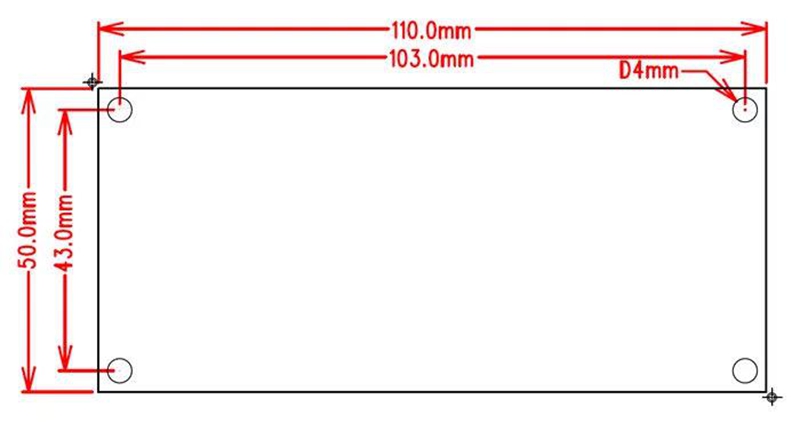
- Size: L x W x H = 110 x 50 x 23mm
- Net weight: 70g
- Battery connector: lock wire terminal
- Input/output connector: lock wire terminal
Charging Characteristics:
- Charging voltage: 4 - 23V continuously adjustable
- Charging current: 0.5 - 5A continuously adjustable
- Trickle charging current: 1/10 of charging current
- End-of-charge current: when the charging current drops to 1/10 of the set value, charging ends.
- Charging conversion efficiency: > 95%
Output Stabilized-voltage Characteristics:
- Output voltage: 2 - 28V continuously adjustable
- Output current: 8.3A
- Output power: 100W
- Conversion efficiency: > 95%
- Output ripple: < 80mVpp
- Stabilized voltage precision: 2%
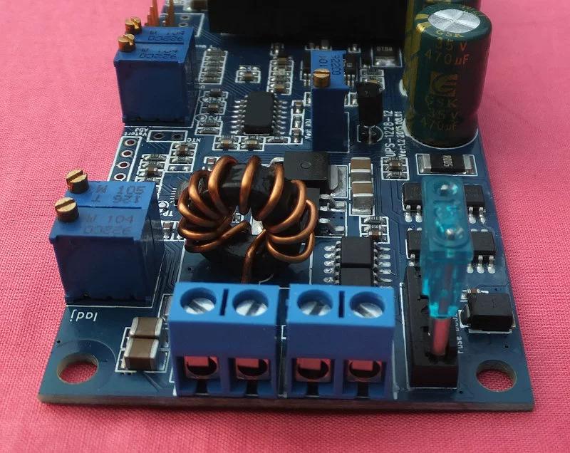
Wiring Diagram: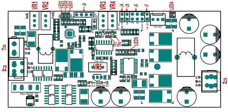
- J1: Battery interface (positive and negative) 5557-2P
- J2: Input power interface 5557-4P
- J3: Output power interface 5557-4P
- J4: Motherboard on/off control output. When it is used as a backup power supply for the computer, the module can control the motherboard to turn on and off through J4, and send instructions to the motherboard to shut down when the battery is under voltage.
- J5, J7:
J7 open circuit (by default): J5 closed, power on; disconnected, power off. Each time the power is turned on, J5 needs to be disconnected and then closed again to turn on the power.
J7 short circuit: J5 closed, power on; disconnected, power off. When powered on, as long as J5 is closed, it automatically starts the power.
Users can choose the appropriate startup method based on practical requirements.
- J6: Delay setting jumper. This jumper is only applicable when the load is on the computer motherboard, and is not set in other situations (i.e. mode 0).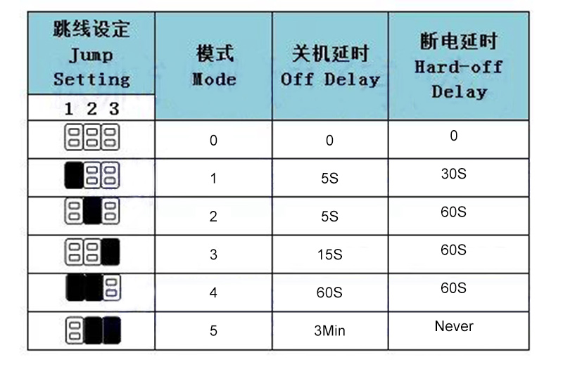
- J8: The external lead out terminal of LED1-LED3 is led out from this socket when an external LED is required.
- VR1: Charging current adjustment potentiometer
- VR2: Charging voltage regulation potentiometer
- VR3: Battery start threshold voltage adjustment potentiometer
- VR4: Battery undervoltage protection threshold voltage adjustment potentiometer
- VR5: Output voltage regulation potentiometer
- LED1: Input power indicator light, blue. Illuminates when the input power supply is normal
- LED2: Light on after charging is completed, red, and light off during charging
- LED3: Light on during charging, green, and light off after charging is completed. It flashes when the battery is discharged and the battery voltage drops below the starting threshold voltage VSTART. When starting the power supply, if the battery voltage is lower than the undervoltage protection threshold voltage VUVP, the power supply cannot be started, and this light flashes twice to indicate battery undervoltage.
- LED 4: Output voltage indicator light, red, light on when there is output voltage; light off when the output is turned off.
Using Instruction:
- Before using this module, please read the following instructions carefully to avoid unnecessary losses. Setting incorrect charging voltage, charging current, and output voltage will damage the module, battery, and even the load. Before wiring, do not confirm the positive and negative polarity of the battery or power supply, as incorrect or reversed connections may cause damage to the module or battery.
Connect the input power supply properly:
- The voltage of the input power supply should be at least 1V higher than the charging cutoff voltage of the battery, otherwise it cannot be charged. For example, if the charging cut-off voltage of a 12V lead-acid battery is 13.8V, then the input power supply should be selected from a power supply above 14.8V, such as 16V, 19V, or 24V.
Adjust the charging voltage:
- Without connecting to the battery, use a multimeter to monitor the voltage at the battery end of the module, and adjust the potentiometer VR2 on the board to ensure that the charging voltage meets the requirements of the battery being used. Turn down the charging voltage clockwise and increase it counterclockwise.
- When adjusting the charging voltage, it should be noted that the charging voltage is constantly changing, which is a pulse voltage output by the charger when automatically detecting the battery. You just need to adjust the highest voltage to the appropriate value. Do not connect the battery to adjust the charging voltage, otherwise it will burn out the module or battery.
- Different batteries have different charging cut-off voltages. Please adjust according to the battery specifications. The charging cutoff voltage of a typical battery is as follows: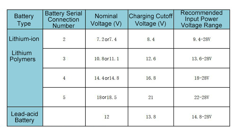
- Note: When the input power voltage is lower than the recommended voltage in the figure, charging will not be possible.
Adjust the charging current (the battery should be fully discharged before adjustment, otherwise the adjustment may not be accurate or the current may not be adjusted up. If the battery capacity is too small, it may also cause the current to not be adjusted up):
- Connect the battery after adjusting the charging voltage. Use an ammeter to serially connect it to the positive pole of the electrode. Rotate the charging current adjustment potentiometer VR1 and observe the ammeter to adjust the charging current to the appropriate value. Turn down the charging current clockwise and increase it counterclockwise.
- Batteries with different capacities have different charging currents. Generally, the fast charging current is 0.3-0.4 times the battery capacity, and the slow charging current is about 0.2 times the battery capacity. For example, a lithium battery is 10aH, and the charging current for fast charging can be set to: 10aH x 0.4=4A, with a charging time of approximately 2.5 hours. The slow charging current can be set to: 10aH x 0.2=2A, charging time is approximately 5 hours. The specific charging current should also be based on the specifications provided by the battery manufacturer.
Adjust the battery startup threshold voltage VSTART:
- The battery startup threshold voltage VSTART is 4 times the voltage of the test point TP3, and the following formula is used for calculation:
VSTART = VTP3 x 4 (V)
- Adjust VR3 and use a voltmeter to monitor the voltage of test point TP3, adjust it to the appropriate value.
- The typical values of different battery undervoltage protection threshold voltage VUVP and startup threshold voltage VSTART are as follows: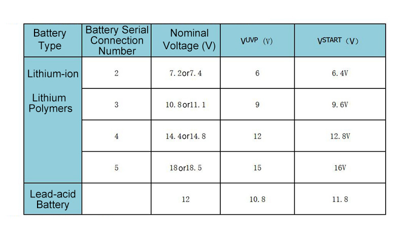
- Users can adjust it according to actual situations.
Adjust the battery undervoltage protection threshold voltage VUVP:
- The threshold voltage VUVP for battery undervoltage protection is 4 times the voltage of TP4 at the test point, and the following formula is used for calculation:
VUVP = VTP4 x 4 (V)
- Adjust VR4 and use a voltmeter to monitor the voltage of test point TP4 to the appropriate value.
Adjust the output voltage:
- Short circuit start switch J5, the voltage regulator module works, and the output power indicator lights on. Adjust VR5 according to the power requirements of the load and adjust the output voltage to the appropriate value. Turn down the output voltage clockwise and increase it counterclockwise.
- The default factory parameter settings for this module are as follows:
Lithium battery, 3 series, 11.1V, 3AH
Charging voltage: 12.6V
Charging current: 1A slow charging
Output voltage: 12V at 8.3A
Battery startup threshold voltage: 9.6V
Battery undervoltage protection threshold voltage: 9V
- Adapters (not included) can be commonly used, such as 16V, 19V, 24V, etc. The power of the adapter depends on the size of the load power. If the output needs to reach a power of 12V/8.3A 100W, the adapter must be at least 130W or above.
Package Included:
- 1 x DC UPS Power Module