| Quantity | 3+ units | 10+ units | 30+ units | 50+ units | More |
|---|---|---|---|---|---|
| Price /Unit | $9.77 | $9.57 | $9.27 | $8.87 | Contact US |
 RT-Thread RA8P1 Titan Board Dual Core 256GOPS High Performance AI-Accelerated MCU Development Board with Camera Module
$101.26
RT-Thread RA8P1 Titan Board Dual Core 256GOPS High Performance AI-Accelerated MCU Development Board with Camera Module
$101.26
 RT-Thread RA8P1 Titan Board Dual Core 256GOPS High Performance AI-Accelerated MCU Development Board
$94.68
RT-Thread RA8P1 Titan Board Dual Core 256GOPS High Performance AI-Accelerated MCU Development Board
$94.68
 XIAO ESP32-S3 & Wio-SX1262 Kit Micro-controller Development Board Support WiFi/Bluetooth/LoRa for Meshtastic
$16.47
XIAO ESP32-S3 & Wio-SX1262 Kit Micro-controller Development Board Support WiFi/Bluetooth/LoRa for Meshtastic
$16.47
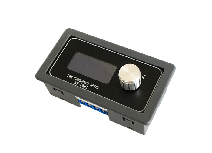
Description:
XY-KPWM signal generator is a device that provides electrical signals at a variety of frequencies, square wave, and output levels.It is used as a signal source or excitation source for testing.Widely used in production practice and technology.
Features:
1>.With outer casing
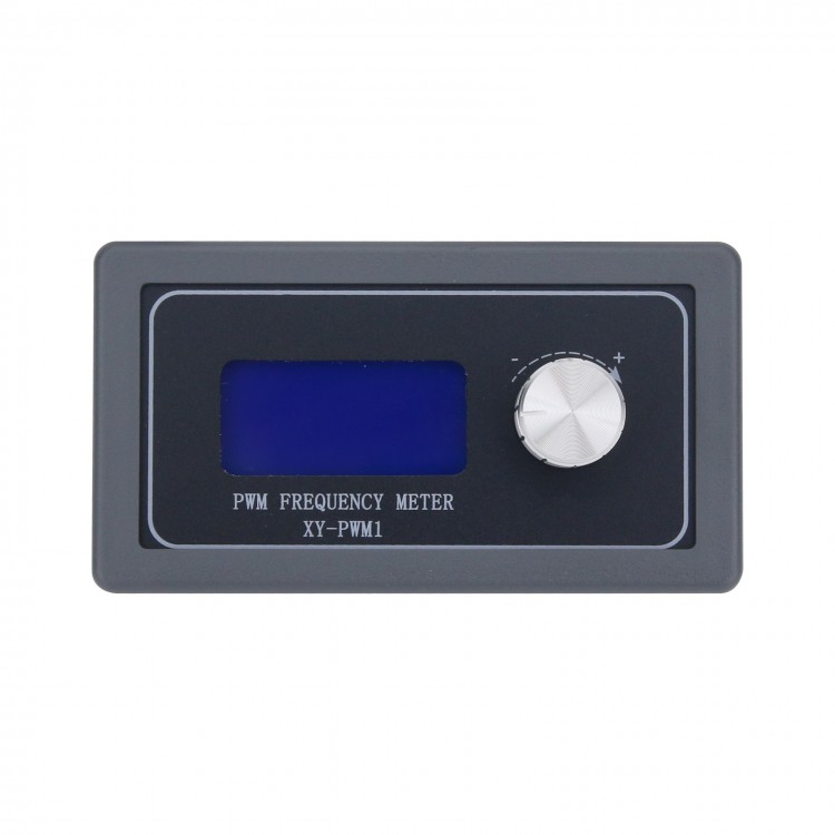
2>.LCD high definition display
3>.Support UART
4>.Support frequency adjustment
5>.Support duty cycle adjustment
6>.High precision detection
7>.Support power-down memory function
8>.1-Channel PWM output
9>.Dual Work Mode
10>.Knob supports lock function to avoid misoperation
11>.Support enable output
3.Parameters:
1>.Product name: XY-KPWM PWM Signal Generator;
2>.Model: XY-KPWM;
3>.Work Voltage:DC 3.3V-30V;
4>.Frequency range(Normal mode):1Hz~150KHz;
5>.Frequency range(Precise mode):1Hz~15KHz;
6>.Frequency accuracy:2%;
7>.Duty cycle accuracy:1% at Normal mode;
8>.Duty cycle accuracy:0.1% at Precise mode;
9>.Duty cycle range:0.00%-100%;
10>.Output Current:About 5-30mA;
11>.Output amplitude:Same to input voltage;
12>.Work Temperature:-40°~85°;
13>.Work Humidity:0%~95%RH;
14>.Size:79*43*37mm;
4.Frequency set range:
There is two work mode so it have two frequency range.
Normal mode:Frequency range 1Hz~150KHz.Duty cycle range 000%-100%.Duty cycle accuracy 1%.
Precise mode:Frequency range 1Hz~15KHz.Duty cycle range 0.00%-100%.Duty cycle accuracy 0.1%.
Enter the settings interface when short press rotary switch in the normal running status to select frequency range.Rotary potentiometer to set frequency value.
Keep press rotary switch for 10second to switch Normal mode and Precise mode.
Keep press for 5second to locking parameters to protect the parameters from being modified.
Pay attention to the position where the decimal point moves when rotary potentiometer..
Display 'XXX'.No decimal point,The minimum frequency is 1Hz.The frequency range is 1Hz ~ 999Hz.
Display 'X.XX'.The decimal point is the penultimate, The minimum frequency is 0.01KHz.The frequency range is 1.00KHz ~ 9.99KHz.
Display 'XX.X'.The decimal point is the third last,The minimum frequency is 0.1KHz.The frequency range is 10.0KHz ~ 99.9KHz.
Display 'X.X.X'.The decimal point is fully lit,The minimum frequency is 1KHz.The frequency range is 1KHz ~ 150KHz.
For Example:
Display '100' means PWM output frequency is 100Hz;
Display '1.91' means PWM output frequency is 1.91KHz;
Display '52.1' means PWM output frequency is 52.1KHz;
Display '1.3.4' means PWM output frequency is 134KHz;
5.Duty cycle set range:
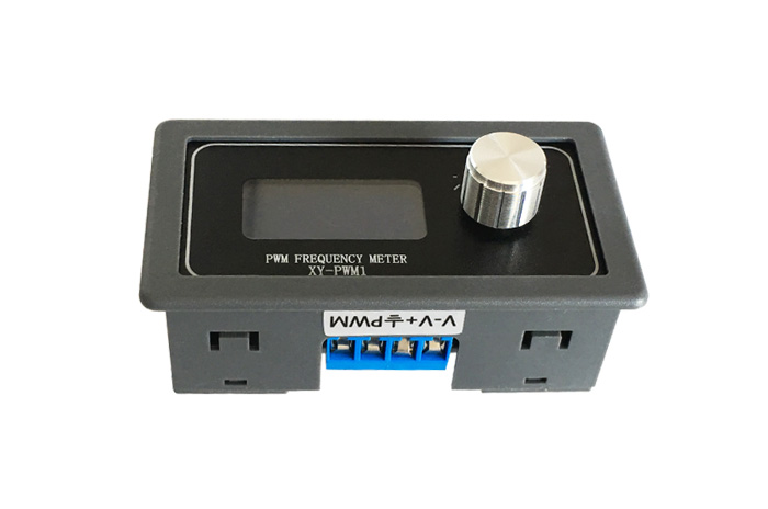
Short press potentiometer to select set duty cycle and rotary potentiometer to set duty cycle value.
6 Use steps:
1>.Connect to power supply;
2>.Press rotary switch for 10second to switch Normal mode and Precise mode;
3>.Short press rotary switch to set frequency and change value by rotating switch;
4>.Press rotary switch for 2second to set duty cycle;
5>.Keep press for 5second to lock set parameters;
6>.Test;
7>.Press button 'ON/OFF' to turn on or off PWM output;
8>.Remove power and connect load to use module.
7.Application:
1>.Square wave signal generator, generating square wave signal for experimental development;
2>.Used to generate a square wave signal that controls the motor driver;
3>.Generate adjustable pulses for use by the MCU;
4>.Dimmer