| Quantity | 3+ units | 10+ units | 30+ units | 50+ units | More |
|---|---|---|---|---|---|
| Price /Unit | $15.88 | $15.55 | $15.07 | $14.42 | Contact US |
 AXera PI Zero Module 5MP AI-ISP Camera Module Designed with SoC Chip AX620Q+SC450AI Image Sensor
$67.98
AXera PI Zero Module 5MP AI-ISP Camera Module Designed with SoC Chip AX620Q+SC450AI Image Sensor
$67.98
 0.5-inch 1024X768 OLED Driver Board High Quality Circuit Board for V760A-5 Wearable Head Mounted Display
$40.24
0.5-inch 1024X768 OLED Driver Board High Quality Circuit Board for V760A-5 Wearable Head Mounted Display
$40.24
 1PCS SFP+ Dual Mode Optical Module Small Form-factor Pluggable Transceiver Support 10Gbps Transmission with LC Interface
$26.09
1PCS SFP+ Dual Mode Optical Module Small Form-factor Pluggable Transceiver Support 10Gbps Transmission with LC Interface
$26.09
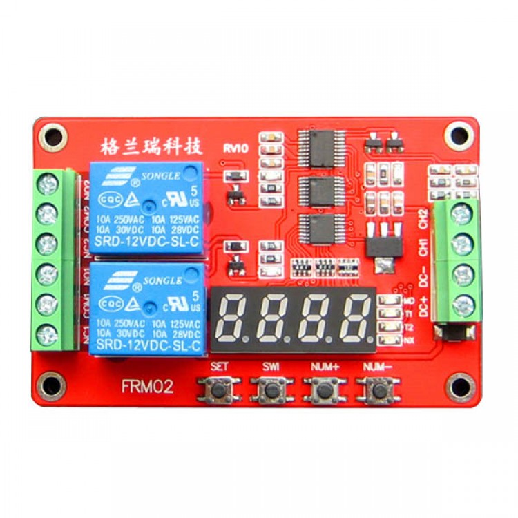
KLR 2 Channel Relay Module with Display High Level Trigger Timer Switch + Self-locking 18 Kinds Model 5/12/24V Power
Module function
- Users can display the key and select the following 18 kinds of functions in one , you can set and save function parameters , you can also view the parameters of the current function of the time parameter sets the minimum 0.1 seconds adjustable accuracy better than 0.01 seconds
- Tips: Function 1-8 start at power on their own , the function requires a high level pulse signal triggers 9-18 start ( high duration shorter than 20ms, hereinafter the same ) , 9 is a self-locking mode function , function 10 is level control mode.
- Function 1 :
Timing Pick : After power-up, the time delay relay T1 , T1 between 0.1 seconds -270 hours adjustable , CH1 interfaces to a high level pulse signal , repeat the above functions ;
- Function 2:
Timing off : When the power relay , time delay relay disconnected T1 , T1 between 0.1 seconds -270 hours adjustable , CH1 interfaces to a high level pulse signal , repeat the above functions ;
- Function 3:
Re- timed pull off : After power relay to not pull, after the delay time T1 reaches relay ; pull off relay T2 arrives after delay time T1 and T2 in 0.1 seconds -270 hours adjustable from CH1 interfaces to a high level pulse signal , repeat the above functions ;
- Function 4:
Then pull off the timing : After power , immediately pull the relay , the relay off after the delay time T1 arrive ; arrive after disconnecting relay time T2, -270 hour in 0.1 seconds delay time between T1 and T2 adjustable , CH1 interfaces to a high level pulse signal , repeat the above functions ;
- Function 5:
Infinite loop timing mode 1: After power relay to not pull, after the delay time T1 reaches relay ; pull off the relay T2 arrives, and then repeat the above condition, the delay time T1 and T2 at 0.1 adjustable seconds between -270 hours, to a high level pulse signal CH1 interface, you can restart the above functions ;
- Function 6:
Infinite Loop Timing Mode 2 : After power , immediately pull the relay delay time T1 reaches the relay off ; arrive after disconnecting relay time T2 , and then repeat the above condition, the delay time T1 and T2 in 0.1 seconds adjustable between -270 hours , to a high level pulse signal CH1 interface, you can restart the above functions ;
- Function 7 :
Finite loop timing mode 1 : After power-up, to not pull the relay after the delay time T1 reaches relay ; pull the relay off time T2 arrive , and then repeat the NX times more than the state , this time in T1 and T2 adjustable between 0.1 seconds -9999 seconds NX cycles adjustable between 1-9999 times , giving a high level pulse signal CH1 interfaces , these functions can be re- started ;
- Function 8:
Finite loop timing mode 2: After power-up, the relay immediately pull delay time T1 reaches the relay off ; arrive after disconnecting relay time T2 , then repeated more times NX state where T1 and T2 at 0.1 adjustable between second -9999 seconds NX cycles adjustable between 1-9999 times , giving a high level pulse signal CH1 interfaces , these functions can be re- started ;
- Function 9:
Latching relay modes: CH1 interfaces to relay a high level pulse signal , the relay , to give a high level pulse signal relay disconnected.
- Function 10:
Trigger relay mode : with delay off function after power relay does not act, a high signal to the CH1 connector , pull the relay immediately after the CH1 signal disappears , the relay still pull, pull time when T1 reaches the relay disconnected, in case T1 is adjustable between 0 seconds -270 hours .
- Note: This feature , if T1 is set to 0 seconds , it becomes : CH1 have high signal relay , no signal is immediately disconnected.
- Function 11:
Pull trigger timing : After power relay does not act, CH1 interfaces to a high level pulse signal , the time delay relay T1 , T1 in adjustable between 0.1 seconds -270 hours , a high-level interface to repeat to CH1 pulse signal , repeat the above function ;
- Function 12:
Disconnect the trigger timing : After power relay does not act, CH1 interfaces to a high level pulse signal , the relay , the relay off delay time T1 , T1 between 0.1 seconds -270 hours adjustable , repeat to CH1 Interface a high level pulse signal , repeat the above functions ;
- Function 13:
Pull the trigger and then disconnect the timing : After power relay does not act, a high-level interfaces to CH1 pulse signal arrives after the delay time T1 relay ; pull off relay arrives after T2 , T1 and delay time T2 is adjustable between 0.1 seconds -270 hours , repeat the interface to a high level pulse signal CH1 , repeat the above functions ;
- Function 14 :
Disconnect and then pull trigger timing : After power relay does not act, the interface to a high level pulse signal CH1 , immediately pull the relay , the relay off after the delay time T1 arrive ; arrive after disconnecting relay time T2 , delay time between T1 and T2 -270 hours adjustable 0.1 seconds , repeat the interface to a high level pulse signal CH1 , repeat the above function ;
- Function 15:
Infinite loop timing mode 1: After power relay does not act, give a high level pulse signal CH1 interface arrive after the delay time T1 relay ; pull the relay off time T2 arrive , and then repeat the above state , the extension when the time between T1 and T2 -270 hours adjustable 0.1 seconds , repeat the interface to a high level pulse signal CH1 , the above function can be restarted ;
- Function 16 :
Infinite Loop Timing Mode 2 : After power relay does not act, CH1 interfaces to a high level pulse signal , immediately pull the relay , the relay off after the delay time T1 arrive ; break time T2 after reaching relay , then repeat the above state , the delay time between T1 and T2 -270 hours adjustable 0.1 seconds , repeat the interface to a high level pulse signal CH1 , the above function can be restarted ;
- Function 17:
Finite loop timing mode 1 : After power relay does not act, CH1 interfaces to a high level pulse signal , the delay time T1 reaches relay ; pull off the relay T2 arrives, and then repeat the above state NX times , this time between T1 and T2 in 0.1 seconds -9999 seconds adjustable , NX cycles adjustable between 1-9999 times , repeating to a high level pulse signal CH1 interfaces , these functions can be re- started ;
- Function 18:
Finite loop timing mode 2 : After power relay does not act, CH1 interfaces to a high level pulse signal , immediately pull the relay , the relay off after the delay time T1 arrive ; break time T2 after reaching relay , then NX repeated more times state where T1 and T2 between 0.1 seconds -9999 seconds adjustable , NX cycles adjustable between 1-9999 times , to a high pulse repetition signal CH1 interface, you can start over again function ;
Two electrical parameters
- Operating voltage : DC 5V, 12V, 24V three options ( should not exceed the nominal voltage of + / -10 % )
- Working current: less than 5V 180mA ( when the relay is not operating less than 15mA, turn off the display of less than 3mA)
- 12V is less than 90mA ( when the relay is not operating less than 15mA, turn off the display of less than 3mA)
- When 24V is less than 60mA ( when the relay is not operating less than 15mA, turn off the display of less than 3mA)
- Working temperature : Recommended -20 -60 degree ( maximum operating temperature range -30 -70 degree)
- Load capacity : Relay normally open port maximum load capacity : DC 0-30V/10A, AC 0-250V/10A
- Relay normally closed port maximum load capacity : DC 0-28V/10A, AC 0-125V/10A
Three module interface
- Module voltage / signal input : 3 -wire interface , all interfaces are terminal, user-friendly
DC +: DC power positive
DC-: negative DC power supply
CH1: Input Signal Detection Interface 1
CH2: Input Signal Detection Interface 2
- Load relay outputs: 3 -wire interface , all interfaces are terminals
NO1: After the first relay normally open interfaces , relay before floating, shorted pull with COM1
COM1: first relay Common Interface
NC1: The first relay normally closed port, COM1 relay shorted before and after the pull- vacant
NO2: After the second relay normally open interfaces , relay before floating, shorted pull and COM2
COM2: second relay Common Interface
NC2: second normally closed relay interface relay short front and COM2 , pull vacant post
Four module sizes:
- Dimensions : 77mm * 50mm * 20mm ( L * W * H )