| Quantity | 3+ units | 10+ units | 30+ units | 50+ units | More |
|---|---|---|---|---|---|
| Price /Unit | $24.77 | $24.27 | $23.51 | $22.50 | Contact US |
 High Precision 17-340Nm Torque Tester Digital Display Torque Meter Support Peak/Track Mode Switch
$33.33
High Precision 17-340Nm Torque Tester Digital Display Torque Meter Support Peak/Track Mode Switch
$33.33
 High Precision 10-200Nm Torque Tester Digital Display Torque Meter Support Peak/Track Mode Switch
$30.22
High Precision 10-200Nm Torque Tester Digital Display Torque Meter Support Peak/Track Mode Switch
$30.22
 High Precision 1.5-30Nm Torque Tester Digital Display Torque Meter Support Peak/Track Mode Switch
$30.22
High Precision 1.5-30Nm Torque Tester Digital Display Torque Meter Support Peak/Track Mode Switch
$30.22
0 to ±5A Current Meter 5-Digit DC Current Meter Featuring High Precision (with Isolated Interface)
Attention:
-
Please refer to the description and wiring diagram below before
purchase and installation. Paper instructions are not provided for the
time being. If the wiring is wrong or improperly used, the meter will be
damaged directly! Please clarify the wiring sequence before connecting!
-
Non-isolated meter adopts a common ground design. The negative pole of
the power supply terminal of the meter and the negative pole of the test
terminal are completely connected. If the same main power supply is
used, its test terminal cannot be connected in series to the positive
pole for testing, which will directly short-circuit the meter. The
measurement must be in-line with the load or ensure no over-current. The
wiring sequence should be: power supply V+->load->test terminal
red wire->test terminal black wire->power GND. The measurement
black wire can only be connected to GND!
- Isolated meter does not
have the above problems, and can be connected to the V+ terminal, or the
GND terminal, or any node in the middle of the circuit to be tested.
Similar to a multimeter, it can measure the current of any node in the
circuit.
Read Before Purchasing:
(1) The interfaces of
our module are clear and its performance is stable. Please combine the
information provided by us and then perform functional verification
corresponding to the experimental conditions.
(2) The basic
parameters of this module are mentioned below. Schematic diagram and
engineering files are not provided. If you have operational problems,
please consult customer service.
(3) Before using the module, please
read the information of this module to understand power supply and usage
restrictions, so as to avoid damage to the module due to improper
operation.
(4) Real module parameters, functions and pictures are provided. All modules have passed inspection before delivery.
Module Parameters:
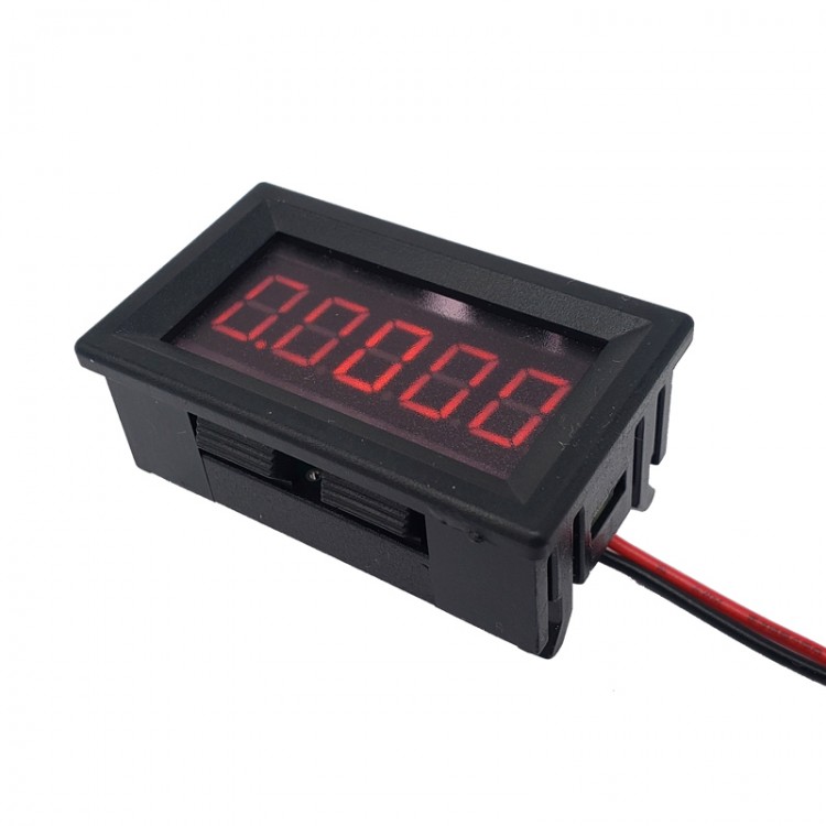
- Module Type: Current Meter
- Supply voltage: 4~30V
- Measuring range: 0~±5A
- Input Impedance: 10mΩ
- Product power consumption: 15mA (min: 14mA; typical: 15mA; max: 16mA)
- Display resolution: 0.1mA
- Measurement accuracy: 0.04%+0.04% [±(reading%+range%) (Tcal 23℃±5℃)]
- Reverse connection protection: yes (reverse connection voltage<=30V)
- Input over0current protection: None (Maximum input current: ±7AC)
- Communication interface: UART_3.3V (9600Baud; 8Bits; None Parity; 1 Stop Bit)
- Communication protocol: for Modbus (support 0X03, 0X06 command C)
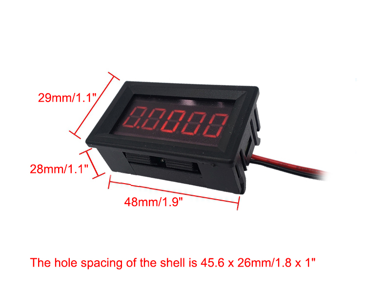
- Module weight: 14.5±1g
- Module size: 29 x 48 x 28mm (tolerance ±1mm)
- Working temperature: -15 to +85℃
Module Description:
-
The ammeter adopts a high-precision reference and sampling resistance
scheme, featuring accurate measurement results and high resolution.
-
It uses a 10mΩ sampling resistor and the input voltage drop is only
50mV when the input current reaches 5A, which has little impact on the
measured system.
- With a bipolar design, it can measure
bidirectional positive and negative currents up to ±5A. It can also
measure the current normally without distinguishing the wiring.
-
Designed with anti-reverse connection circuit. The module does not work
when the power supply is reversed, but this will not cause damage to the
circuit.
- High input overload current. Input current up to 7A will
not cause damage to the circuit. When the current returns to within ±5A,
the module can measure the current value normally without restarting.
-
The module integrates serial communication function, and the current
data of the module can be read back by devices such as single-chip
microcomputer and computer (requires USB to serial port module). The use
of Modbus protocol is convenient for large-scale integration and
industrial applications.
Package Included:
- 1 x Module (with Isolated Interface)
- 2 x Connecting Cables
Note:
- Battery and other items pictured are not included, for demonstration purposes only. Thank you for your understanding!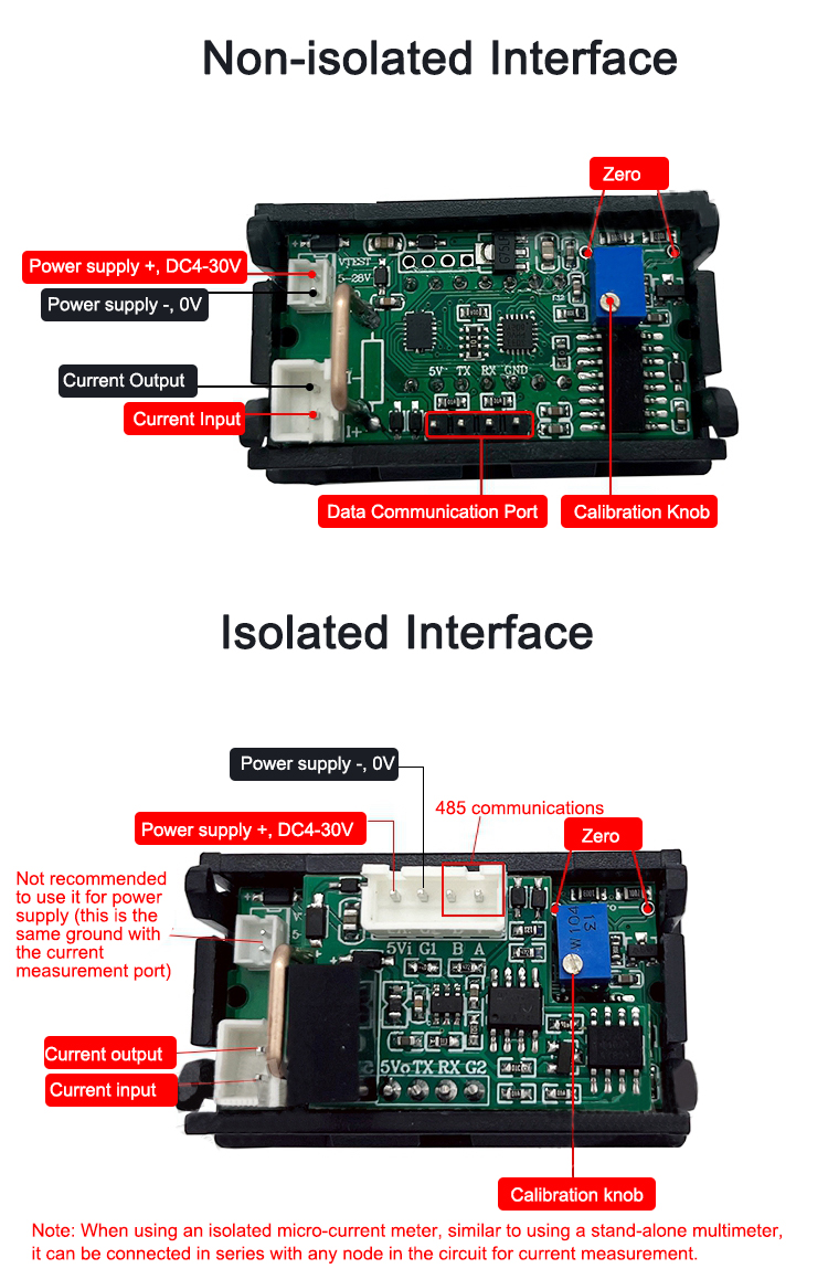
The
module has been zeroed and calibrated. If you use this product for a
long time or the temperature and humidity change greatly, it may drift a
little, and you can perform zeroing and calibration operations on the
back of the circuit board. When the current input line is unplugged, its
display is not 0. At this time, you can short-circuit the two zero
adjustment holes in the figure, and then release the module within about
2S to automatically complete the zero adjustment. The measurement error
caused by long-term use can be adjusted by the Calibration Knob in the
figure.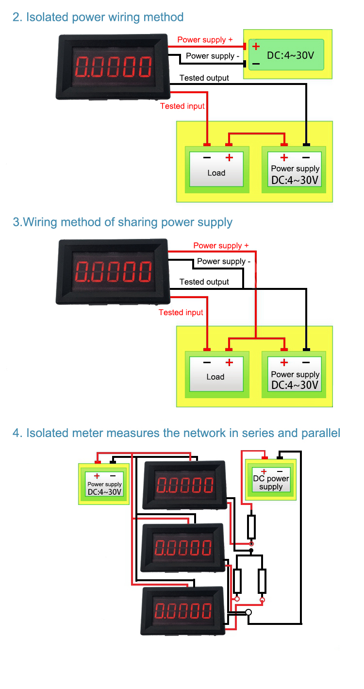
Precautions:
(1) Do not use a power supply that exceeds the nominal supply voltage range to power the module.
(2) The voltage should not exceed 30V when reversely connected.
(3)
The non-isolated meter adopts a common ground design, and its test
terminal cannot be connected to the positive pole in series. The current
loop wiring sequence should be: power supply V+->load->test
terminal red wire->test terminal black wire->power GND. The black
wire of the module measurement can only be connected to the loop GND.
Data Communication Description:
The
module communication interface is UART-3.3VTTL, the communication
protocol adopts Modbus protocol, and supports 0X03 read (single or
multiple consecutive) and OX06 write (single) commands.
FAQ:
Q: What is the situation when the display keeps drifting during current measurement?
A:
When testing the product after receiving the good, the user needs to
ensure the stability of the current to be measured, so that the
stability of the product can be accurately measured. Common errors
collected so far are:
1.Battery is connected in series with
resistance to provide the current to be measured: as the voltage of the
battery gradually decreases during use, the current it generates also
gradually decreases, and the display naturally gradually decreases
(please use a stable power supply to generate current for testing);
2.
Use small package resistors and large resistors to limit current to
generate current: small package resistors often have low power and poor
heat dissipation. When the current is passed, it will gradually become
hot, and the resistance value of the resistor will drift with the
temperature drift. I=V/R, R drifts, and I naturally drifts. The
principle of large resistance current is similar. For example, when 50mA
current to be measured is also required, the larger the resistance
value, the higher the power and the faster the heat generation (it is
recommended to use a high-power small-value resistor to limit the
current to generate the current, such as 50W 50Ω or 50W 50Ω gold-sealed
resistor).
Q: Can it be powered by battery?
A: Yes. The module
has a wide power supply voltage. Battery power can be used as long as
the battery voltage is within the nominal power supply range of the
module.
")
")
")

")


")


