| Quantity | 3+ units | 10+ units | 30+ units | 50+ units | More |
|---|---|---|---|---|---|
| Price /Unit | $99.98 | $97.94 | $94.88 | $90.80 | Contact US |
 High Precision 17-340Nm Torque Tester Digital Display Torque Meter Support Peak/Track Mode Switch
$33.33
High Precision 17-340Nm Torque Tester Digital Display Torque Meter Support Peak/Track Mode Switch
$33.33
 High Precision 10-200Nm Torque Tester Digital Display Torque Meter Support Peak/Track Mode Switch
$30.22
High Precision 10-200Nm Torque Tester Digital Display Torque Meter Support Peak/Track Mode Switch
$30.22
 High Precision 1.5-30Nm Torque Tester Digital Display Torque Meter Support Peak/Track Mode Switch
$30.22
High Precision 1.5-30Nm Torque Tester Digital Display Torque Meter Support Peak/Track Mode Switch
$30.22
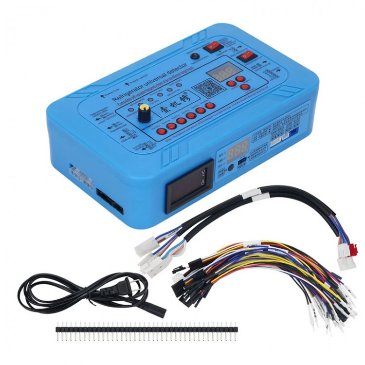
110V Professional Multifunctional Refrigerator Tester Inverter Test and Refrigerator Compressor Tester
Description:
- Application: Single signal inverter board, dual signal inverter board, inverter compressor, single damper, double damper, pulse solenoid valve, 12V electrical switching valve, DC-fan.
- Output voltage: 110V
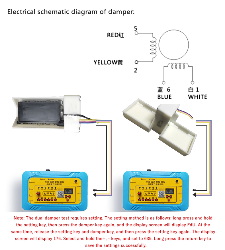
Electrical throttle detection:
- Connect the damper detection line to the damper motor interface in red, yellow, blue, and white order as shown in the figure.
- Note: The default program is a single damper.
- Press the damper button, the damper indicator light will light up, and the display screen will display 176. When the damper is fully open, the damper indicator light off. Press the damper button again, the damper indicator will light up, and the display screen will display 176. When the damper is completely closed, the damper indicator light off. If the damper opens and closes smoothly, it indicates that the air door is normal. If the damper does not rotate, does not open or close smoothly, or if there is a problem, it indicates that the damper has failure.
Electrical switching valve detection:
- Connect the electric valve to the detector as shown in the figure, press and hold the electric valve key for 3-5 seconds, the display screen will display - 0, and the valve core will return to the starting position. At this time, the inlet is connected to port A. Press the electric valve button once, and the display screen shows - 18. At this point, the inlet is connected to Port B.
- Press the electric valve button for the second time, and the display screen shows - 36. At this time, the inlet is connected to port C. Press the electric valve button for the third time, and the display screen shows - 54. At this time, the inlet is connected to the BC port. After the above tests, it can be determined that the electric valve is in good condition if it switches normally. If there is no switching action of the electric valve, it indicates that the electric valve is faulty.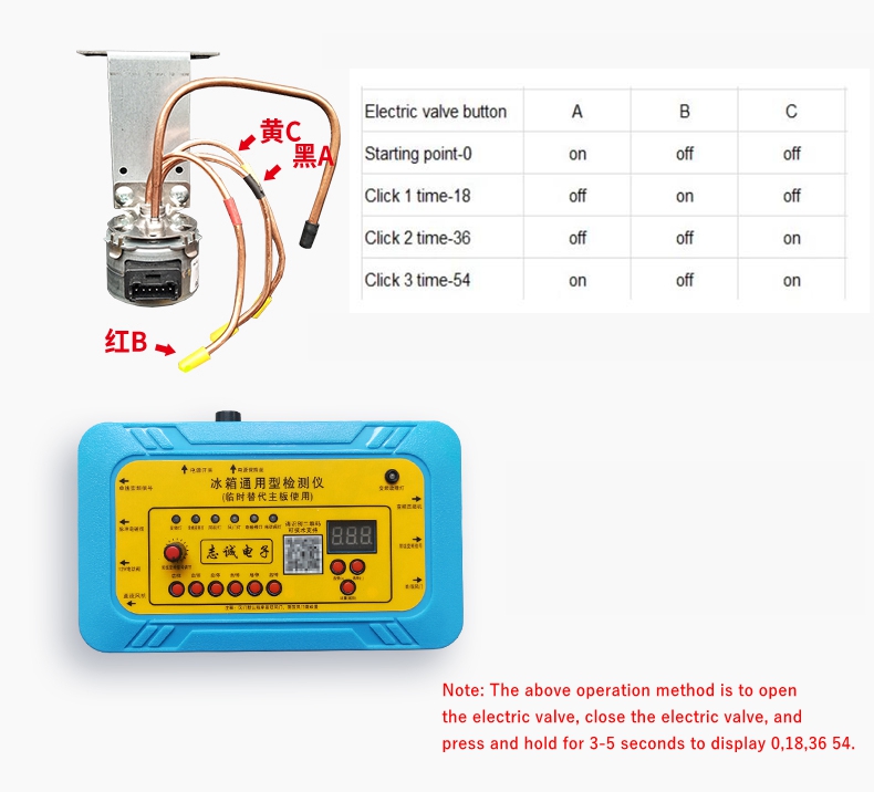
DC-fan detection:
- Connect the DC fan to the detector in the order of positive (+), negative (-), and feedback as shown in the figure. Press the fan button, and if the fan speed is normal, the display screen will display the real-time feedback signal frequency (speed) of the fan to determine its integrity. If the fan does not rotate or displays E1 after 10 seconds, it can be determined that the fan is faulty.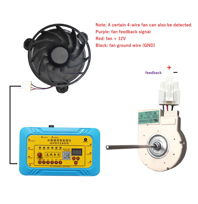
Dual steady-state pulse solenoid valve detection:
- Connect the solenoid valve detection line to the solenoid valve interface as shown in the figure. Press the solenoid valve button and the display screen will display 10, indicating a positive pulse. Press the solenoid valve button again and the display screen will display -10, indicating a negative pulse. You can hear the solenoid valve making a clicking directional sound, and if there is no directional sound, it can be determined that the solenoid valve is faulty. (Attention! The solenoid valve detection line outputs a pulse voltage, please do not touch it when using. The solenoid valve detection line outputs a pulse voltage, and the DC voltage range of the multimeter measures around 100V.)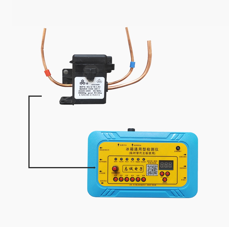
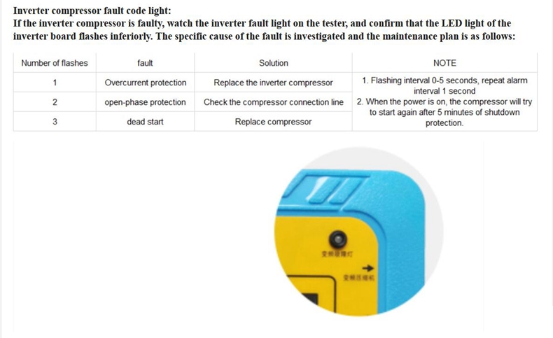
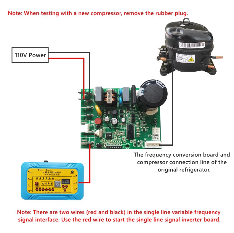
Single line signal inverter:
- Connect the detection line of the inverter board to the communication interface of the inverter board as shown in the figure, then connect the output end of the inverter board to the compressor, and then supply 110V power to the inverter board. Press the single line inversion signal button, the detector outputs a startup signal, and the compressor can be started, eliminating each issue one by one. (Attention! The frequency conversion board is all normal. If it does not start, please use the compressor detection function to test the compressor and eliminate it one by one. Once the compressor is started, it needs to wait for more than 5 minutes for the system pressure to balance before testing again.)
Dual line signal inverter:
- Connect the detection line of the frequency conversion board to the communication interface of the frequency conversion board (positive and negative need to be distinguished) as shown in the figure, then connect the output end of the inverter board to the compressor, and then supply 110V power to the inverter board. Press the dual wire signal inverter key, and the detector slowly performs automatic frequency increase to reach the set frequency. When the variable frequency compressor is started, it can be eliminated one by one. If: when the frequency is set at 40-50Hz, it will rise at a frequency of 1Hz per second until the set frequency is reached. (Attention! The inverter board is all normal. If it does not start, please use the compressor detection function to test the compressor and eliminate it one by one. Once the compressor is started, it needs to wait for more than 5 minutes for further testing, and wait for the system pressure to balance before testing again.)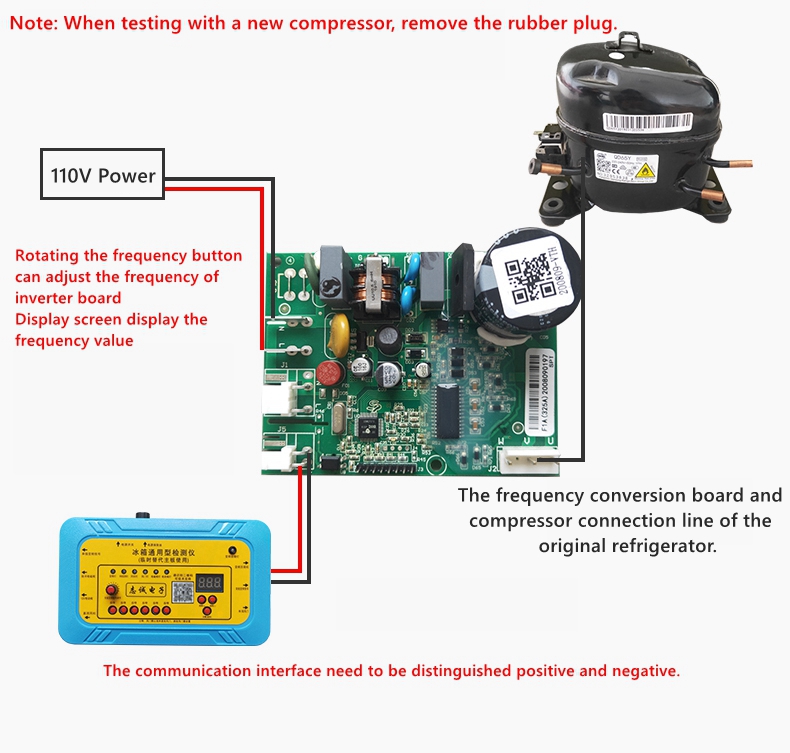
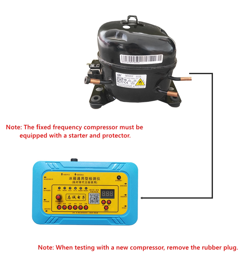
Fixed frequency compressor detection:
- Connect the compressor detection line to the refrigerator compressor as shown in the figure, and press the single line inverter signal button. Output voltage: 110V, the compressor can be directly started. If the compressor does not start, it can be determined that the compressor is faulty. (Attention! Once the compressor is started, wait for more than 5 minutes for further testing, and wait for the system pressure to balance before testing again.).
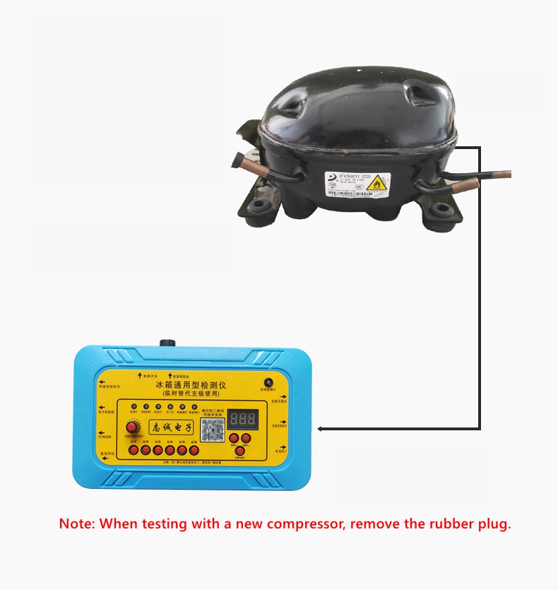
Variable frequency compressor detection:
- Connect the compressor detection line to the refrigerator variable frequency compressor as shown in the figure, press the dual wire signal inversion key, and the detector slowly performs automatic frequency increase to reach the set frequency. When the variable frequency compressor is started, it can be eliminated one by one. If: when the frequency is set at 40-50Hz, it will rise at a frequency of 1Hz per second until the set frequency is reached. If the compressor does not start, it can be determined that the compressor is faulty. (Attention! Once the compressor is started, wait for more than 5 minutes for further testing.)
Package Included:
- 1 x 110V Detection Kit