| Quantity | 3+ units | 10+ units | 30+ units | 50+ units | More |
|---|---|---|---|---|---|
| Price /Unit | $11.80 | $11.56 | $11.20 | $10.72 | Contact US |
 H2MD DC24-120V 6A Engraving Machine CNC Stepper Motor Driver Module Support Phase Dislocation Protection
$45.54
H2MD DC24-120V 6A Engraving Machine CNC Stepper Motor Driver Module Support Phase Dislocation Protection
$45.54
 ZM-3H2080 24V High Performance 3-Phase Stepper Motor Driver Controller AC80-220V for 86-130MM Stepper Motors
$166.32
ZM-3H2080 24V High Performance 3-Phase Stepper Motor Driver Controller AC80-220V for 86-130MM Stepper Motors
$166.32
 ZM-3H2080 12V High Performance 3-Phase Stepper Motor Driver Controller AC80-220V for 86-130MM Stepper Motors
$166.32
ZM-3H2080 12V High Performance 3-Phase Stepper Motor Driver Controller AC80-220V for 86-130MM Stepper Motors
$166.32
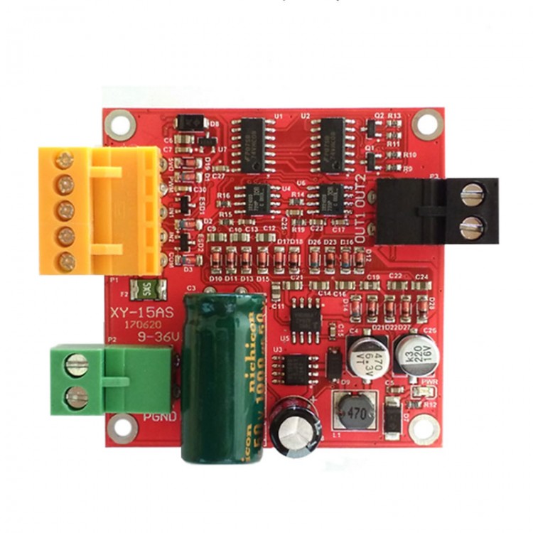
15A High Power DC Motor Driver Board Module Industrial Grade CW CCW PWM Speed Control
Features:
- Industrial-grade design, stable and reliable, with anti-static circuit, transient suppression protection, under-voltage protection, interface ESD and over-voltage protection, etc.
- Support a wide range of voltage 9-36V, the maximum continuous load current 12A (without heat dissipation), 15A (simple heat dissipation), 20A (thick large heat sink)
- Similar to L298 drive logic, three wires (PWM, IN1, IN2) can be used to control speed, CW, CCW and brake
- Support full PWM. You can directly use buttons to control CW and CCW. Effective range of PWM is 0.1% ~ 100.0%
- Can provide 5V power supply for MCU and other controllers. With 5V output over-current protection and access signal over-voltage protection
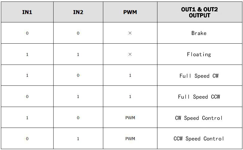
Control Signal Logic:
Note: 0 is low level, 1 is high level, x is any level, and it is low level when floating.
COM is signal ground and 5VO is 5V output, which can provide 5V power for controllers such as MCU.
PWM pin can be connected to external PWM. If you use button control mode, the PWM pin should be connected with 5VO. IN1 and IN2 are control signals for CW, CCW and braking of two motors.
Specifications:
- Supply voltage 6V-36V (When voltage is too low, load current is large and the module is easily damaged, so the circuit board is marked as 9-36V). Power supply must not be reversedly connected or exceed 37V, otherwise the module may be damaged. It is recommended to connect a 20A fuse in series with power input end.
- When the driver is not cooling, rated current is 12A. For rated currents of 12A to 15A, simple heat dissipation is required. For 15A to 20A, thick heat dissipation device is required. (Simple heat dissipation: You can use a 1mm thermal silicone pad under the module, and then use a 5mm copper pillar to fix the module to the device wall).
- Control signal interface (orange) can provide users with 5V externally. MCU does not need additional power supply, the maximum power supply current is 0.5A.
- High-level voltage of control signal: 2.0V ~ 5.5V, compatible with 3.3V and 5V TTL levels;
Low voltage of control signal: 0V ~ 0.8V, 0V when floating;
When control signal voltage is 5V, control signal current is 50uA.
- PWM effective range: 0.1% ~ 100.0%;
PWM signal frequency range: 0 ~ 100KHz (20KHz is recommended);
Minimum PWM effective pulse width: 200ns.
- Working temperature: -25℃ to 80℃
- Size: 55 * 55 * 25mm (L*W*H)
- Installation hole diameter: 3mm
- Weight: 38g
Parameters of Compatible Motors:
Users are required to do simple heat dissipation or thick heat dissipation accessories according to motor parameters.
1. Motor with a rated voltage of 36V
Marked rated power of ≤300W, or marked rated current of <12A. Motors can work at full capacity for a long time, without heat dissipation.
Marked rated power 300W ~ 370W, or marked rated current 12A ~ 15A. Motors need to do simple heat dissipation treatment.
Marked rated power 370W ~ 500W, or marked rated current 15A ~ 20A. Motors needs thick and large heat dissipation treatment.
2.Motor with rated voltage of 24V
Marked rated power ≤200W, or marked rated current <12A. Motors can work at full capacity for a long time, without heat dissipation.
Marked rated power 200W ~ 250W, or marked rated current 12A ~ 15A. Motors need to do simple heat dissipation treatment.
Marked rated power 250W ~ 330W, or marked rated current 15A ~ 20A. Motors needs thick and large heat dissipation treatment.
3. Motor with rated voltage of 12V
Marked rated power ≤70W, or marked rated current <12A. Motors can work at full capacity for a long time, without heat dissipation.
Marked rated power 70W ~ 90W, or marked rated current 12A ~ 15A. Motors need to do simple heat dissipation treatment.
Marked rated power 90W ~ 120W, or marked rated current 15A ~ 20A. Motors needs thick and large heat dissipation treatment.
(The rated current of the driver is 12A when it is not equipped with heat dissipation part. When rated current is 12A to 15A, it is necessary to perform simple heat dissipation treatment. For 15A to 20A, thick heat dissipation treatment is required. The rated power marked on motors generally refers to output power. Consider the motor work loss, so motor efficiency must be considered when calculating rated current. Rated current = rated power/rated voltage/efficiency).
Using Method:
1. Wiring method for controlling motor rotation using MCU
The power supply ground of MCU is connected to the COM of the driver module. PWM pin is connected to the PWM output of MCU for speed regulation or directly connected to high level for full speed operation. IN1 and IN2 are connected to two IOs of MCU to control CW, CCW and braking of motors. 5VO can provide 5V power for MCU.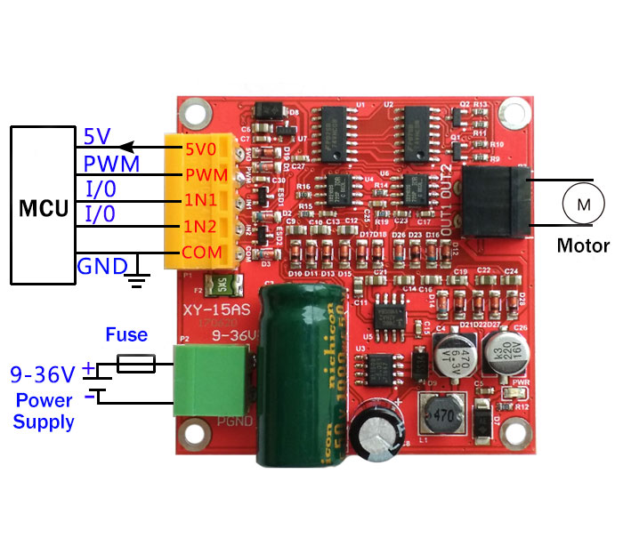
2. Wiring method for controlling motor CW CCW via button only
PB1 and PB2 are two buttons. When PB1 is pressed and PB2 is not pressed, IN1 is high level and IN2 is low level, and motor is in CW mode. When PB2 is pressed and PB1 is not pressed, IN1 is low level, IN2 is high level, and motor is in CCW mode. When PB1 and PB2 both pop up, both IN1 and IN2 are low level, and motor is braked. 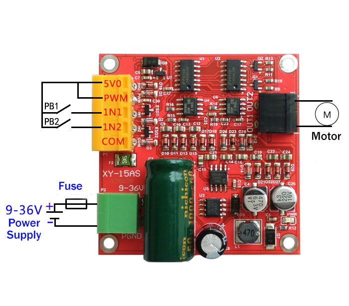
3. Wiring method of using our store's PWM generator to control motor speed
PWM generator can be set by keys. You can select frequency and duty cycle, and control motor speed. PB1 and PB2 are two keys that respectively control the direction of motor rotation. When both PB1 and PB2 are popped up, motor is in braking state. If PWM generator is needed, please contact us. 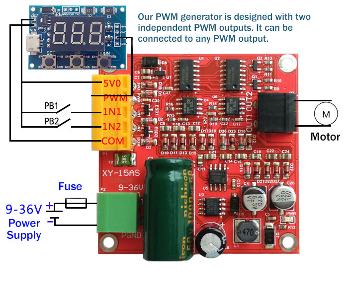
Precautions:
1.Driver power voltage should be 6-36V. If it is over-voltage, the driver may be burned after power-on. If voltage is too low and load current is large, the driver may be burned. It is recommended to connect a 20A fuse in series at the power supply.
2.When switching between CW and CCW, it is better to brake more than 0.1S before CCW, otherwise the driver may be damaged.
3.Because control signal cable is very fragile, any signal cable (orange wiring terminal) of control signal cannot be overlapped with the wires of power supply or motor interface while using. Otherwise, it is very likely to burn the drive and it is difficult to repair.
4.When the driver is powered off, do not rotate your motor quickly. Otherwise, the electromotive force generated by the motor may burn the driver. If application requires your motor to rotate quickly when the driver is powered off, it is recommended that a relay be connected in series with the motor interface of the driver. Relay coil and the driver share power supply. In this way, when power supply fails, the relay will disconnect the driver from the motor.
5.The driver should be connected to motor before it is powered on, otherwise fuse or the driver may be burned.
6.Motor interface must not be short-circuited, otherwise fuse or driver may be burned.
7.Not to get the driver wet, or short circuit the components on the driver board, and not touch the pins and pads of the components on the board with your hand.
8.Please read the above descriptions carefully before application.
Package Included:
- 1 x DC Motor Driver Board


 PLUS Ackerman Robot Car Top-End Version w/ Independent Suspension Orin NX 8GB + C16 Lidar")
")


