| Quantity | 3+ units | 10+ units | 30+ units | 50+ units | More |
|---|---|---|---|---|---|
| Price /Unit | $97.76 | $95.77 | $92.78 | $88.79 | Contact US |
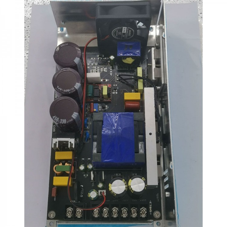
2KW ±65V ±80V ±96V ±110V Full-Bridge LLC Amplifier Power Supply Board Switching Power Supply Board
Specifications:
* Item name: 2000W full-bridge LLC amplifier switching power supply board
* Size: 240 x 123 x 65mm/9.4 x 4.8 x 2.6" (for reference only, subject to the actual product)
* Weight: about 1.08KG/2.4LB (for reference only, subject to the actual weight)
* Input: AC200~240V
Packaging Details:
* G.W.: 1.20KG/2.6LB
Package Included:
* 1 x Amp Power Supply Board
Note:
* ±80V board will be delivered by default.
Read before Purchasing:
* Before placing an order, please select a voltage. In the case of no load, the output voltage jumps a little, which is a normal phenomenon. The reason for this phenomenon is that the no-load chip works in intermittent power-on mode. Users can add a dummy load of about 10W to solve this problem, but this will increase heat generation and reduce efficiency.
* In addition, when there is no load, there is a certain error in the positive and negative voltages, which is a normal phenomenon. Please make sure that you don't mind before purchasing, because the switching power supply voltage regulation is to control the +VCC. Compared with -VCC, this way is added with power-consuming components such as optocoupler 431, because -VCC has no other power-consuming components, so the voltage at both ends of the -VCC filter capacitor is the peak virtual electricity. Although there is a bleeder resistor on the board, it is not possible to target all output voltages. There is a slight deviation but it does not affect the use. Users can also add a bleeder resistor such as 10K and 33K between -VCC to ground. Users needs to experiment to decide which resistor to add the appropriate resistance value until they are satisfied with the positive and negative voltages.
Attention:
* The switching power supply is mainly used to control the principal voltage. The the principal voltage must be used with an auxiliary voltage with a certain load. If the main voltage is unloaded, the chip will think that the output voltage of the switching power supply has arrived, and the chip will be turned off. It is impossible to use only the auxiliary part without the principal voltage.
* Principal voltage output: take ±110V as an example, that is, +110V, 0V and -110V.
* The auxiliary voltage is DC±12V 0.5A, and the output is three terminals, that is, +12V, 0V and -12V (when the main voltage has a load of 10-20W, the auxiliary voltage will be normal).
* A fan can be mounted to its shell. Continuous heavy loads require a fan to dissipate heat.
* Solid aluminum sheet 10mm/0.4" in thickness is used as a heat sink.
* This is a switching power supply that can fine-tune voltage. Its highest output voltage is its best. When the voltage is lowered and the load is relatively light, it is easy to cause the switching power supply to enter the intermittent mode from the fixed pulse width mode, and the intermittent mode will inevitably lead to the change of the pulse width. If some power amplifier board noise suppression is not good, it is easy to lead to static noise. The solution is actually very simple. Add a dummy load between the output + VCC and the ground, such as adding a high-power cement resistor. The specific scheme needs to be decided through experiments, because different boards will be different. The maximum output voltage of the switching power supply board must be lower than 90% of the withstand voltage of the power amplifier board, so the waveform of the switching power supply is the cleanest when it is static at the maximum voltage output.