| Quantity | 3+ units | 10+ units | 30+ units | 50+ units | More |
|---|---|---|---|---|---|
| Price /Unit | $37.79 | $37.02 | $35.86 | $34.32 | Contact US |
 Gravity Waves BLACK DOMAIN Tube Amp Attenuator Dummy Load Box for Tube Amplifiers ≤200W
$143.04
Gravity Waves BLACK DOMAIN Tube Amp Attenuator Dummy Load Box for Tube Amplifiers ≤200W
$143.04
 Gravity Waves Tube Amp Bunker Tube Guitar Amp Attenuator Load Box and Cab Sim Combo (Silver)
$414.91
Gravity Waves Tube Amp Bunker Tube Guitar Amp Attenuator Load Box and Cab Sim Combo (Silver)
$414.91
 20W Gravity Waves Bluespace White All-Tube Guitar Amplifier Guitar Tube Amp Combo with Stand & Pedal
$1,490.66
20W Gravity Waves Bluespace White All-Tube Guitar Amplifier Guitar Tube Amp Combo with Stand & Pedal
$1,490.66
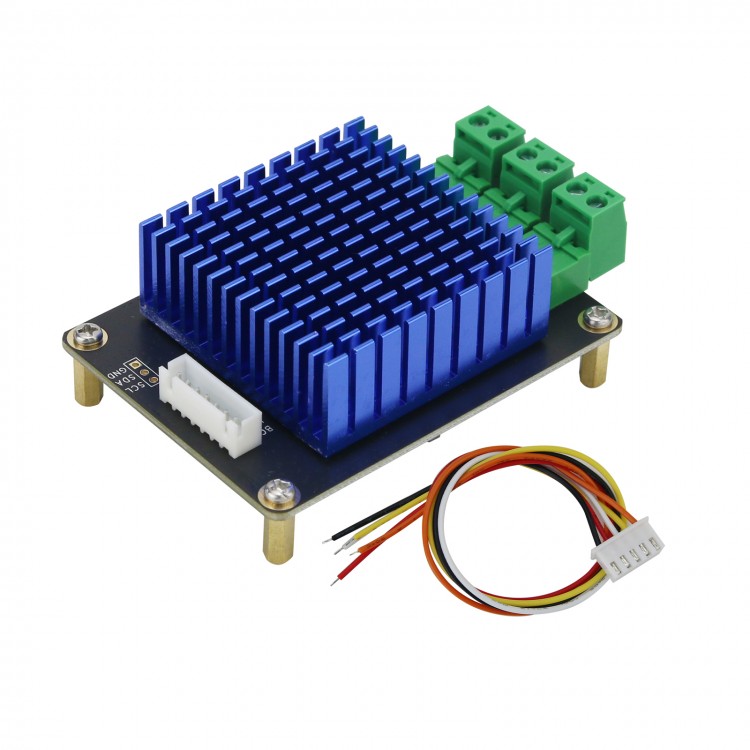
PL-AD-160 High Quality HIFI Digital Class D Power Amplifier Module 2x80W MA12070 Digital IIS Input
Description:
PL-AD-160
is a high-end digital power amplifier product based on MA12070
solution. MA12070 is a highly efficient fully integrated digital audio
power amplifier IC based on multi-level switching technology. With
enhanced design and production standards, the PL-AD-160 series of
products can ensure high reliability and stability throughout the entire
life cycle. It can provide first-class audio performance in a small
package, suitable for design engineers to develop products for home and
professional audio applications.
Features:
1.
Multi-level switching technology with 3-level and 5-level modulation
makes the solution unparalleled in power consumption and energy
efficiency-optimized for power consumption when playing music, making it
extremely low energy consumption.
2. 2x80W peak output power (26V
PVDD, RL = 4Ω, 10% THD+N level), an ultra-compact, highly integrated
solution-a real high-power small body.
3. Flexible realization of 2.0
(2*80W), 2.1 (1*80W+2*40W), 4.0 (4*40W), 1.0 (1*160W) channel output
level configuration through the on-board dip switch.
4. The
fourth-order feedback error control can provide better gain and suppress
errors better than the traditional second-order loop, thereby ensuring
extremely low signal distortion and excellent audio performance, even if
the power supply is not ideal (noise or ripple), still ensuring low
distortion, high sound quality and stability and reliability.
5.
<160mW idle power dissipation (26V PVDD, all channels are switched);
when the power is 2W, the efficiency is >80% (1kHz sine wave, 8Ω);
when the power is full power, the efficiency is >91% (1kHz sine wave,
8Ω).
6. Audio performance (PMP2): >110dB SNR (A-w, relative to 1%
THD+N power level), without the need for complex dynamic follow-up
power supply design (conventional audio power design solutions that
improve energy efficiency).
7. 45µV output integrated noise (A-w), no low-pass filter (LPF) is required in most applications.
8. When the output level is high, THD+N is 0.004%.
9.
I2C control (four optional addresses for the DIP switch on the board),
which can be connected to the MCU to control the working mode of the
chip, achieving a balance between performance and power consumption, and
can be customized in various applications.
10. Built-in protections:
undervoltage lockout, overheat warning/error, short circuit/overload
protection, power stage pin to pin short circuit, error report via
serial interface (I2C), and DC protection.
11. Four-layer immersion gold PCB + anodized heat sink, with excellent heat dissipation and extremely low EMI.
12. Module size: 80 x 60 x 35mm (LxWxH)
Applications:
1.
Portable speakers: battery powered speakers (battery is not included),
mobile Bluetooth speakers, docking speakers, portable speakers, wearable
speakers
2. Home audio: multi-room system, TV, sound column, home theater system, independent components
3. Voice control speaker
4. Professional audio: active monitor speakers, Power over Ethernet (PoE), multi-channel system
Advantages and Working Principle of Multi-Level Technology:
Although
the efficiency of the traditional Class D audio amplifier has reached
90% and above, its relatively high power only achieves about 50% of the
usual volume efficiency, and its demand for LC filters and heat sinks
makes It takes up a lot of space (and the cost is higher). Multi-stage
Class D amplifiers break these limitations. Its technological innovation
has brought the following advantages:
› No need to output LC filter, smaller size and lower cost
› Improved common volume efficiency
› Significantly reduce power consumption and reduce heat dissipation
›
Thanks to the high-frequency multi-level switch, the details of the
sound source are preserved and the sound quality is improved.
This
breakthrough amplifier product uses a multi-stage half-bridge power
stage to achieve low power consumption in standby or near standby.
Unlike traditional Class D amplifiers, each half-bridge power stage of
this product has 4 transistors/MOSFETs (traditional Class D amplifiers
only have 2pcs). These half bridges establish multiple PWM output stages
through a single power supply (each MOSFET is driven by a separate PWM
signal), which brings great flexibility and can configure the amplifier
for the best power performance in any application. The flying capacitor
(Cfly) located between the top and bottom MOSFETs is continuously
powered by an independent circuit, so the voltage potential can be
maintained at a fixed level. This "flying capacitor" basically acts as
an additional power rail. In this way, each half-bridge power stage can
establish a three-level output signal at the output switching node: 0 V,
½ PVDD, and PVDD.
1.
DC power supply input terminal. The interface sequence from top to
bottom is: VIN+, GND, VIN+, GND, two VIN+ and two GND are connected on
the board to facilitate module cascading. The maximum input voltage of
VIN+ is DC +26V, and the absolute voltage exceeding +27.5V will
permanently damage the chip! To ensure the output power, please use a
power supply of 200W and above. The minimum input voltage of VIN+ is
+4V, and it is actually recommended to use a power supply above 6V.
2.
Analog audio signal input terminal. The interface sequence from top to
bottom is: IN0A, IN0B, GND, IN1A, IN1B, corresponding to the audio input
terminals of SPEAK0A, SPEAK0B, SPEAK1A, and SPEAK1B respectively. The
overall board gain is 20dB by default.
3. External control
communication input terminal. The interface sequence from left to right
is: SCL (clock pin of IIC), SDA (data pin of IIC), GND (ground), EN (the
chip enters the reset state when pulled high), MUTE (mute output,
effective when pull low).
4. IIC address selection pin, used to
control multiple chip selection IIC addresses when multiple modules are
used in parallel. Bit 1: AD0, bit 2: AD1.
5. Chip working mode selection. Bit 1: MSEL1, Bit 2: MSEL0. (Push up means 1)
Bit1/Bit2=0/0:
4-channel single-ended output (SE), at this time the maximum output
power of each channel is 40W. The connection method is shown in the
figure below:
Bit1/Bit2=0/1:
2 channels of single-ended output (SE) + 1 channel of half-bridge
output (BTL), at this time, the power of each channel of single-ended
output is 40W, and the power of half-bridge output channel is 80W. The
connection method is shown below:
Bit1/Bit2=1/0:2-channel
half-bridge output (BTL), at this time, the output power of each
channel is 80W (factory default setting). The connection method is shown
below:
Bit1/Bit2=1/1:1
channel dual half bridge output (PBTL), at this time, the single
channel output power is 160W. The connection method is shown in the
figure below:
6. Audio power level output terminal. The interface sequence from top to bottom is: SPEAK0A, SPEAK0B, SPEAK1A, SPEAK1B.
7.
Power supply indicator LED. Green or blue LED, this LED should always
be on after power on, indicating that the power supply of the module is
normal.
Module Use Steps:
1. Correctly set the DIP switch at position 5 and correctly connect speaker hardware.
2. Set the voltage correctly at the interface 1 and connect DC power supply, you can see the LED at position 7 is lit.
3. Connect the input audio source to the interface 2 correctly.
4. Other parts generally do not need to be connected to work normally.
Package Included:
- 1 x Power Amp Module
Note:
- Green PCB pictured is for reference only. The actual items are designed with Black PCB boards.
- Items in Red or Black will be delivered at random. Please make sure that you don't mind before purchasing.
- Battery is not included.