| Quantity | 3+ units | 10+ units | 30+ units | 50+ units | More |
|---|---|---|---|---|---|
| Price /Unit | $42.36 | $41.49 | $40.19 | $38.47 | Contact US |
3-Band AM FM Signal Generator Radio Signal Generator Wireless Transmitter for Electronics Enthusiast
Description:
The signal generator is a small device that can generate and emit electromagnetic waves. It is mainly used to repair and tune radios. Its main function is to emit electromagnetic waves of different frequencies for radio to receive, which is convenient for radio debugging.
The FM range is about 76-108MHZ, and there is a separate 10.7MHz IF signal output. The AM medium wave frequency range is 400kHz-1610kHz, including intermediate frequencies 450khz and 465khz. Shortwave frequency range is 5MHz-18MHz.
There is a sine wave inside the device with an audio of about 800Hz-1100Hz. External audio signal is also supported. The adjustment system can be adjusted. It can transmit signals wirelessly and wired output is supported. There is a 3.5mm socket to output high-frequency signal and low-frequency signal. It can also be used as a signal injector, which is a practical tool for repairing, assembling and debugging radios.
The transmission distance of AM MF is about 2m/6.6ft. The transmission distance for shortwave and FM bands is about 10m/32.8ft. The above distances are for reference only.
Experimental AM FM Transmitter:
- This is an experimental small home wireless transmitter through which audio signals such as mobile phones can be transmitted and received with a regular radio. It can be connected to an external microphone and used as a small wireless microphone. The machine has four frequencies that can transmit. They are 90M, 105M, 12M and 1000KHz. You can select any of the frequencies to transmit. Transmission distance is 10-20m/32.8-65.6ft. It can be used as a reference for electronics enthusiasts to learn the knowledge of wireless transmission.
- It is only suitable for ordinary home indoor use, and should not interfere with others in public places.
Package Included:
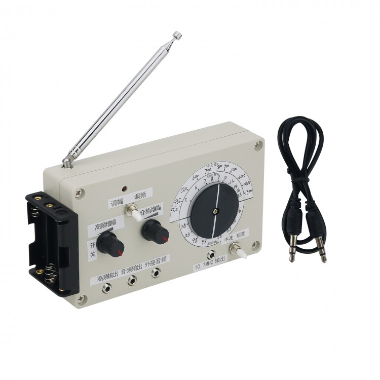
- 1 x Signal Generator
Note:
- Battery is not included in the package.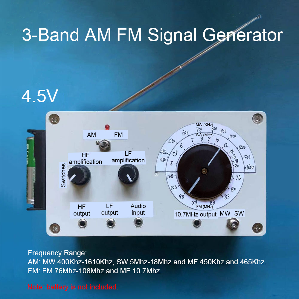
How to Use 3-Band AM FM Signal Generator?
1. Install 18650 batteries in the battery box. Toggle the power switch on the HF amplification knob, and the power indicator will be on, which means that the power has been turned on.
2. Toggle the band switch to select bands. The bands are divided into amplitude modulation band and frequency modulation band. Amplitude modulation bands are divided into two bands: medium wave (MW) and short wave (SW). The lower end of the dial is a SW and MW selector switch. Move to MW for the MW band and move to SW for the SW band. The telescopic antenna should be pulled out for the FM band and SW band.
3. Rotate the frequency dial to a desired frequency. The upper half of the frequency dial is the medium-wave and shortwave frequencies, and the lower half is the frequency modulation frequency. After selecting the band and adjusting to the desired frequency, let the radio also tune to the corresponding band and frequency position, and the audio sound should be received. The size of the modulation can be adjusted by adjusting audio amplification knob. The reception is best when the modulation system is appropriate.
4. Audio output port can output the audio signal in the machine. The amplitude of the output signal can be adjusted by adjusting the audio amplification knob.
5. The audio input port can be connected to external audio signals. Connecting external audio, the audio signal size and signal modulation can be adjusted by adjusting the audio amplification knob. At this time, the internal audio will be automatically disconnected.
6. When the 10.7MHz IF signal is output in the FM band, connect an output cable to radio IF transformer, and listen to the sound while debugging the IF transformer, until the radio is muted, indicating that the IF transformer has been adjusted to 10.7MHz.
HF amplification knob: Adjust this knob to adjust the output signal size of the high-frequency output jack. It is mainly used for wired output.
Audio amplification knob: Adjust this knob to adjust the output signal size of the audio output jack. When transmitting wirelessly, this knob can adjust the modulation of the high-frequency signal so that radios can receive the best results.
465kHz IF Signal & Audio Signal Injection Method:
Turn the signal generator to the MW band, the dial points to the 465kHz position, and the high-frequency output will output 465kHz IF signal. Inject this IF signal into the superheterodyne radio's mid-amplification and frequency conversion levels, and for silent faulty machines, you can see where the signal is not passing. For machines that have sound but want to adjust the MF frequency, you can adjust the MF transformer step by step. In addition, the signal generator is emitting a signal at this time. As long as the signal generator is close to a radio magnetic antenna, the intermediate frequency signal can be connected to the frequency conversion level and the sound with audio signal can be heard. Theoretically, radio can receive the IF signal in the entire frequency range, because the rejection of the IF signal by the antenna coil is limited, but the sound is smaller. It is possible to simply bring the signal generator close to the radio antenna and adjust the IF transformer step by step to get maximum sound.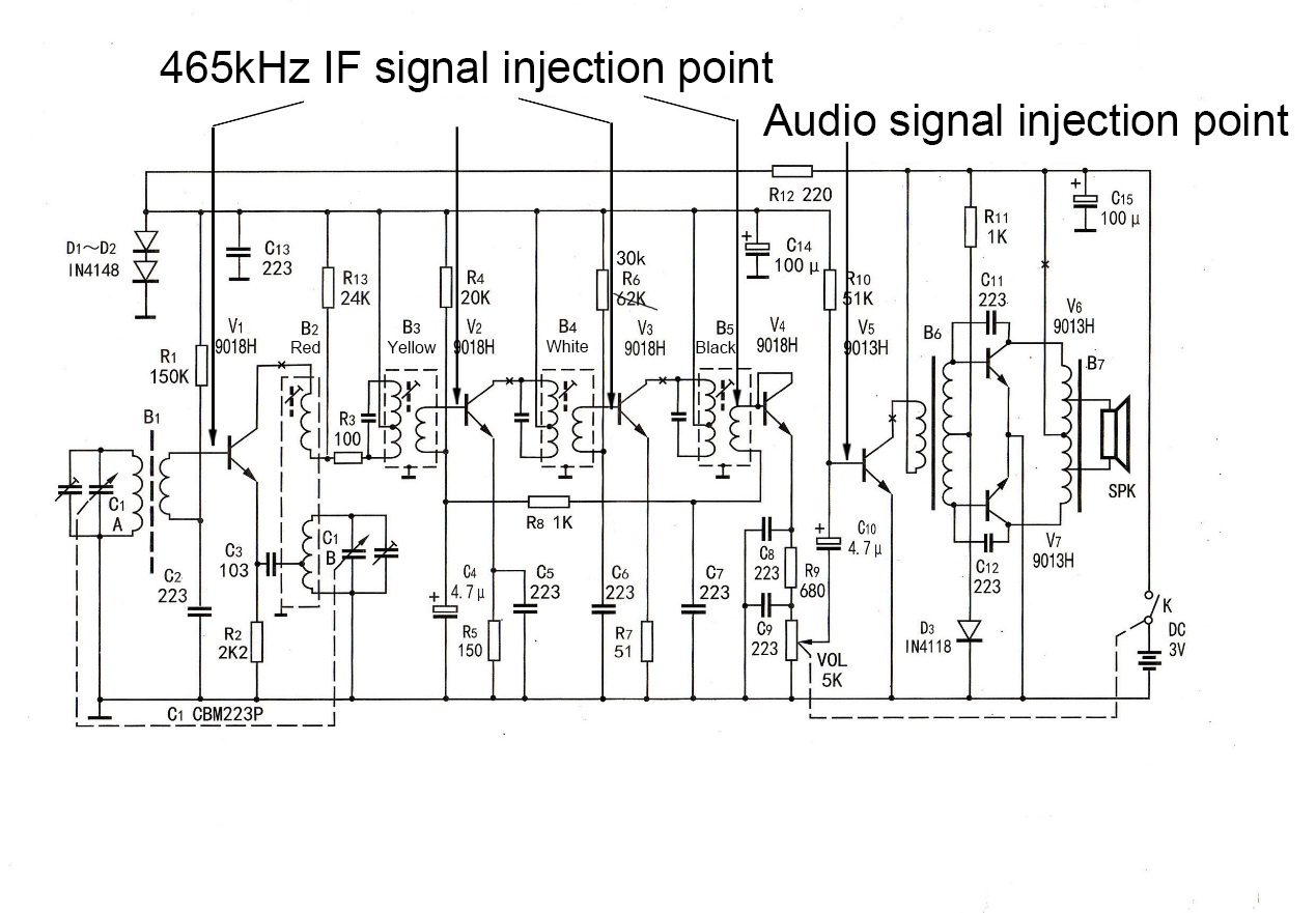
For the radio low-frequency amplification stage inspection, the audio signal can be output from the audio output interface of the signal generator, and the fault point can be easily found by connecting the audio signal to the low-frequency amplification stage and checking it one by one.
How to Use FM 10.7MHZ IF Signal Source?
The following is a debugging reference circuit.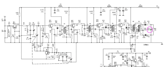
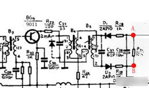
- Referring to the above circuit, the 10.7mhz intermediate frequency signal is injected from the base of the first intermediate frequency transformer BG2, and one end is grounded. Use a multimeter to monitor the voltage on the C29 A and B, that is, the output voltage.
- Adjust the magnetic core of the first IF transformer to make the voltage of points A and B reach the maximum;
- After adjusting the magnetic core of the second IF transformer to make the voltage of points A and B reach the maximum, adjust the magnetic core by 0.005mm in the direction of large inductance to broaden the low-end bandwidth of the IF transformer.
- After adjusting the magnetic core of the third IF transformer to make the voltage of points A and B reach the maximum, adjust the magnetic core by 0.005mm in the direction of small inductance to broaden the high-end bandwidth of the IF transformer.
- Adjust the magnetic core of the first intermediate frequency transformer to make the voltage of points A and B reach the highest;
- Adjust the magnetic core of the second intermediate frequency transformer to make the voltage of points A and B reach the highest and the sound is not distorted. You can also hear the sound to mute, which means that the intermediate frequency transformer has been adjusted. Different radio circuits are similar, please refer to this circuit.
How to Debug a Radio with a Signal Generator?
1. Adjust the intermediate frequency transformer first.
Wireless output of 900kHz signal with signal generator. Receive the signal generator signal with a radio and carefully adjust the magnetic core of the IF transformer with a non-inductive screwdriver until the sound is at its maximum. Appropriately widen the distance between the radio and the signal generator, and adjust the 3 intermediate frequency transformers (do not adjust the oscillating coil) step by step from back to front according to the above method to make the radio sound loudest. In this way, the medium frequency is adjusted.
The intermediate frequency transformer is adjusted very messily, and when the signal generator signal cannot be received, the signal generator can output an intermediate frequency 465kHz signal, close to the radio or the wired output to the radio intermediate frequency transformer, and debug the intermediate frequency transformer to make the sound the largest. This method starts with eliminating the absence of other faults in the radio.
2. Frequency modulation coverage
The frequency range can only be adjusted when the IF transformer is adjusted and the radio is loud. Turn the signal generator dial to the low end of 530kHz, output a low end signal, also turn the radio to the low end of the frequency, and then adjust the magnetic core in the oscillating IF transformer (the red one closest to the variable capacitor) until the radio receives the 530KHz signal. Turn the signal generator dial to the high end of 1610KHz, output a high end signal, then adjust the radio to the high end of the frequency, and adjust the fine adjustment capacitor on the variable capacitor oscillation link until the radio receives a frequency of about 1610KHz. Then fine-tune the adjustment end to fine-tune the capacitor so that the sound is the loudest, and the high and low end need to be adjusted several times.
For the FM band, use an FM signal generator. First set the radio to the low end of the frequency 87MHz, adjust the oscillation inductance (the one with the lowest number of turns) until 87MHz appears, then turn the radio to the high end of the frequency 108MHz, and adjust the fine adjustment on the pins of the variable capacitor connected to this inductor until the 108MHz frequency appears. It needs to be repeated several times.
3. Three points unified adjustment
Keep the signal generator appropriately away from the radio until the radio receives the signal from the signal generator. At the low end of the frequency, adjust the position of the magnetic rod coil until the sound is maximum. At the middle end of the frequency, adjust the position of the magnetic rod coil until the sound is maximum. At the high end of the frequency, adjust the fine adjustment on the pins where the variable capacitor connected to the magnetic rod coil is located, and then adjust the position of the magnetic rod coil until the sound is the maximum. Repeat the above operation several times until the sound of the high, medium and low points can be even.