| Quantity | 3+ units | 10+ units | 30+ units | 50+ units | More |
|---|---|---|---|---|---|
| Price /Unit | $13.38 | $13.10 | $12.69 | $12.15 | Contact US |
 SUP-C703S Signal Generator & Process Calibrator – mA, V, Ω, RTD, Thermocouple Output & Measurement
$156.44
SUP-C703S Signal Generator & Process Calibrator – mA, V, Ω, RTD, Thermocouple Output & Measurement
$156.44
 6000A 20µH Air Core Inductor for Dual Pulse Testing and High-Performance Electrical Experiments
$86.76
6000A 20µH Air Core Inductor for Dual Pulse Testing and High-Performance Electrical Experiments
$86.76
 DP8000 Max IGBT Pulse Generator with Internally Integrated IGBT Driver (Air Core Inductor Included)
$384.16
DP8000 Max IGBT Pulse Generator with Internally Integrated IGBT Driver (Air Core Inductor Included)
$384.16
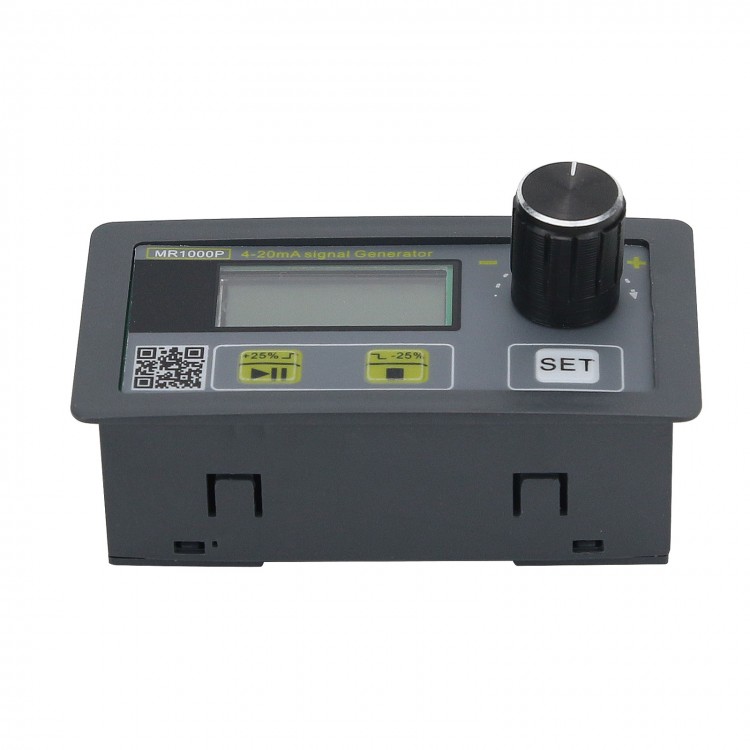
4-20mA Signal Generator Passive Signal Generator Calibration Device Analog Transmitter
Parameters:
- Power Supply: 10-30V
- Output Signal: 4-20mA
- Minimum Resolution: 0.01mA
- Accuracy: 0.2%
Package Included:
- 1 x Signal Generator
Three Working Modes:
- Mode 1: Manual adjustment of analog quantity. Voltage/current value can be adjusted by the knob to follow the change in real time.
- Mode 2 (PC): Automatic rise and fall linear output. According to the maximum and minimum values of set parameters, the product will complete the change from the minimum value to the maximum value within a specified period, and the cycle continues.
- Mode 3 (PS): Automatic step up and down output. According to the maximum value and minimum value of set parameters and the value of each step increase or decrease, the product will complete the change from the minimum value to the maximum within the specified period, and the cycle continues.
Parameter Settings (Press  for 3s to enter menu shown as bellow):
run: Working mode. Multiple choice
SHEn: Engineering quantity enable (only valid when analog quantity is manually adjusted). Setting range OFF/ON
SH-H: The upper limit of engineering quantity. Setting range: -1999 to 9999, the default is 100.0
SH-L: Lower limit of engineering quantity. Setting range: -1999 to 9999, the default is 0.0
SH-P: The position of the decimal point of the engineering quantity. 0-2
SAEn: Automatically save the set value flag. Setting range OFF/ON
AUTO: Parameter setting for automatic rise and fal. Multiple choice
----Exit the menu
Parameter Modification:
- Rotate the knob to select parameters, and press SET button to enter parameter modification.
- Press SET to save the modified parameter value.
- Value setting: Press the knob and turn to select the number of digits to be set.
Detailed Explanation of Multiple Choice Menu:
run: Working mode.
Adjust the knob to run, press SET button to enter, there are three options:
4-20mA: manual mode
PC (Mode 2): Automatic up down linear output
PS (Mode 3): Automatic step up and down output
Using Method:
Rotate the knob to select input mode. After pressing SET button, the meter will automatically exit the menu and enter the working mode immediately.
If you select Mode 2 or Mode 3, the meter is in a paused state and you need to press the start key to start working.
AUTO: Parameter Setting for Automatic Up and Down
Adjust the knob to AUTO, press SET key to enter, the parameters are as follows:
Po-L: Automatic rise and fall minimum value, the setting range is the signal range of the corresponding model
Po-H: the maximum value of automatic rise and fall, the setting range is the signal range of the corresponding model
Po-M: Automatic up and down waveform mode. First rise and then fall, rise, fall, three modes are optional
PC-S: Time setting of automatic rise and fall linear output (PC)
PS-S: Time and step value of automatic rise and fall stepping output (PS)
----Return to superior
Detailed Explanation of Time Setting Parameters of PC-S Automatic Rise & Fall Linear Output (PC):
PCT1 cycle, coefficient 1, maximum 9999, unit: second
PCT2 period, coefficient 2, maximum 9999, unit: second
PCSt starts the PC program directly
----Return to superior
Coefficient Description:
One rise and fall cycle=PCT1*PCT2.
The two coefficients are to increase the length of time, because only 4 digits are available.
For example, PCT1=60, PCT2=1, period 60*1=60 seconds, Po-M=first rise and then fall sequence. At the beginning of the program, the output is the Po-L value, after 30 seconds it rises to the Po-H value, and then it drops to the Po-L value from 30 seconds, so that a process completes a cycle.
Po-M=First rise and then fall sequence. At the beginning of the program, the output is the Po-L value, after 30 seconds it rises to the Po-H value, and then it drops to the Po-L value from 30 seconds. This process completes a cycle.
Po-M= rising sequence, the program output is the Po-L value at the beginning, after 60 seconds, it rises to the Po-H value, and then immediately jumps to the Po-L value, so that a process completes a cycle.
Po-M=decline sequence, the program output is Po-H value at the beginning, after 60 seconds, it drops to Po-L value, then immediately returns to Po-H value, such a process completes one cycle.
Detailed Explanation of Time Setting Parameters of PS-S Automatic Rise & Fall Step Output (PS):
PST1 cycle, coefficient 1, maximum 9999, unit: second
PST2 cycle, coefficient 2, maximum 9999, unit: second
PSSU step value. The setting range is the signal range of the corresponding model
PSSt directly starts the Ps program
----Return to superior
Coefficient Description:
A signal value step time=PST1*PST2.
The two coefficients are to increase the length of time because only 4 digits are available.
For example, PST1=4, PST2=1, PSAU=4.00, step time 4*1=4 seconds.
Po-M=First rise and then fall sequence. At the beginning of the program, the output is the Po-L value. After 4 seconds, it increases by 4.00, and then cyclically increases to the Po-H value, and then cyclically decreases to the Po-L value. This process completes a cycle.
Po-M = rising sequence, the program outputs the Po-L value at the beginning, after 4 seconds it increases by 4.00, and then increases to the Po-H value in a loop, and then immediately jumps to the Po-L value, so that a process completes one cycle.
Po-M=decline sequence, the output of the program is the Po-H value at the beginning, after 4 seconds, the decrease is increased by 4.00, and then the cycle is reduced to the Po-L value, and then it immediately jumps to the Po-H value, such a process completes a cycle .
Calibration:
After the device is powered on, it is connected to a meter, and current value can be measured normally, and then press and hold  for 3s to enter calibration menu.
Rotate the knob to calibrate the point, press to enter the modification, and press again after modification.
20CA: Calibrate 20ma. Modify this parameter to 20ma.
4CA: Calibrate 4ma. Modify this parameter to 4ma.
----Exit
After adjustment, save and exit!