| Quantity | 3+ units | 10+ units | 30+ units | 50+ units | More |
|---|---|---|---|---|---|
| Price /Unit | $247.83 | $242.77 | $235.19 | $225.07 | Contact US |
 T90C (T65 Tip) Portable Intelligent Soldering Iron IPS LCD Screen 18-130W Soldering Pen with PD 140W Adapter and T65-KU/BC2 Tips
$82.62
T90C (T65 Tip) Portable Intelligent Soldering Iron IPS LCD Screen 18-130W Soldering Pen with PD 140W Adapter and T65-KU/BC2 Tips
$82.62
 T90C (T65 Tip) Portable Intelligent Soldering Iron IPS LCD Screen 18-130W Soldering Pen with PD 140W Adapter
$72.87
T90C (T65 Tip) Portable Intelligent Soldering Iron IPS LCD Screen 18-130W Soldering Pen with PD 140W Adapter
$72.87
 T90C (T65 Tip) Portable Intelligent Soldering Iron IPS LCD Screen 18-130W Constant Temperature Soldering Pen with TH10 Stand
$48.42
T90C (T65 Tip) Portable Intelligent Soldering Iron IPS LCD Screen 18-130W Constant Temperature Soldering Pen with TH10 Stand
$48.42
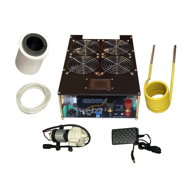
5000W Induction Heater Kit w/ Mainboard Heating Coil 150mL Crucible Water Pump & 12V 2A Power Supply
Advantages:
* Input Voltage: DC 12–60V
* Maximum Power: 5000W
* With a 2.4" Color LCD Screen
* One-Key Reset
* One-Key Start
* Under-voltage Set Point (UVP)
* Over-current Set Point (OCP)
* Low Water Pressure Protection
* Microsecond-Level Under-voltage & Over-current Protection
* Anti-Interference External Control Interface: Compatible with PLC, microcontroller, and other secondary development systems
Description:
The 5KW induction heater boats a built-in power meter to simplify operation. The system features microsecond-level over-current and under-voltage protection, water shortage protection, and displays the protection type directly on the screen.
This product is a low-power induction heater powered by a DC 48V 60A power supply. It is mainly used for heating and quenching small iron-based metal materials.
By default, a 60mm diameter heating coil is included.
When used with the matching graphite crucible, it allows easy melting of metals such as iron, copper, gold, silver, and aluminum.
Product Features and Functions:
* Designed with 1.6mm thick military-grade PCB, 20oz copper thickness, high current capacity, and excellent heat dissipation
* Equipped with four 9025 cooling fans
* Uses a custom oversized high-power heatsink to ensure efficient cooling of the MOSFETs
* The output terminal uses 12 parallel M4 copper posts, which can be connected not only to a heating coil but also to a high-voltage transformer or high-frequency transformer
* Resonant circuit consists of 10 original IRFP260 MOSFETs and 24 original BM capacitors in parallel, delivering high power and high efficiency
* This product can operate continuously for extended periods under adequate cooling conditions
* Integrated design of power meter and control system for ease of use
* Integrated control reduces the need for complex wiring
* The heating coil is wrapped with high-temperature insulation material to prevent short circuits during the heating process
* Built-in microsecond-level fast over-current protection: once overloaded, the heating circuit is automatically shut off for protection
* A color LCD screen displays all system working parameters, including voltage, current, power, working status, and alarm types. The potentiometer allows setting of the maximum allowable working current and minimum input voltage. If exceeded during operation, the system will immediately enter overload protection mode and lock operation, requiring manual reset before restarting.
* Button control with optional external foot switch, suitable for various applications
* Water cooling system includes water shortage protection
2.4-Inch Color LCD Screen Displays:
* Input Voltage
* Input Current
* Input Power
* Operating Status
* Alarm Types
Product Specifications:
* Dimensions: 307mm × 210mm × 96mm
* Operating Voltage: DC 12V–60V (DC 48V recommended)
* Maximum Operating Voltage: 60V DC
* Maximum Power Output: 5000W
* Maximum Operating Current: 100A
* Heating Coil Inner Diameter: 60mm
Attention:
* During use, always monitor the display for changes in parameters, especially voltage, current, and mainboard temperature. If any abnormality is detected, immediately disconnect the power.
Packing List:
* 1 × Mainboard
* 1 × Heating Coil
* 1 × 150mL Crucible
* 1 × Water Pump
* 1 × Water Pump Hose
* 1 × DC 12V 2A Power Supply
Packaging Details:
* Weight: 4.8KG
Safety Precautions for Use:
1. Under no circumstances should the system be powered on without a load (no load means the output terminals are not connected to any load). Powering on without a load will cause high-frequency noise and may result in irreversible damage to the MOSFETs.
2. Induction heating operates at high power. In addition to heat generated by the PCB and electronic components, the heating coil also produces significant heat. To avoid burning the heating coil and affecting the entire system, a dedicated cooling water pump must be used with the coil.
3. It is recommended to use a power supply with sufficient power. Otherwise, under-voltage protection may be triggered during operation. The power supply must exceed:
* 800W for 12V
* 1500W for 24V
* 3000W for 36V
* 5000W for 48V
No matter the voltage, as long as the operating current stays below 100A, the circuit will not be damaged. You can set the maximum current to 100A using the potentiometer. High-power operation inevitably generates heat, so proper heat dissipation is essential.
4. The under-voltage threshold must not be set below 12V, and the over-current threshold must not exceed 100A. Again, good cooling is necessary due to inevitable heat from high-power operation.
5. During operation, the heating coil produces extremely high temperatures. It is recommended to use water cooling to reduce the coil's temperature to avoid damage to the mainboard. If possible, use a non-recirculating system with cold water in and hot water discharged directly into the drain.
6. The power input terminals are marked with + and –. Do not reverse the polarity!
7. Do not power on without a load (here, no load means the output is not connected to any load. Connecting a heating coil without heating an object does not count as no load).
8. When using a graphite crucible, a non-recirculating water cooling system must be used—cold water in and hot water out to the drain—to prevent high water temperature from reducing service life. This method is also recommended for extended high-power operation. After heating, if the crucible remains inside the heating coil, never disconnect the 12V auxiliary power; otherwise, the water pump will stop, and the heating coil may be damaged by the crucible's residual heat.
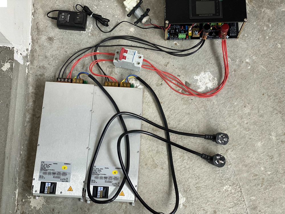
Interface Description (as shown below):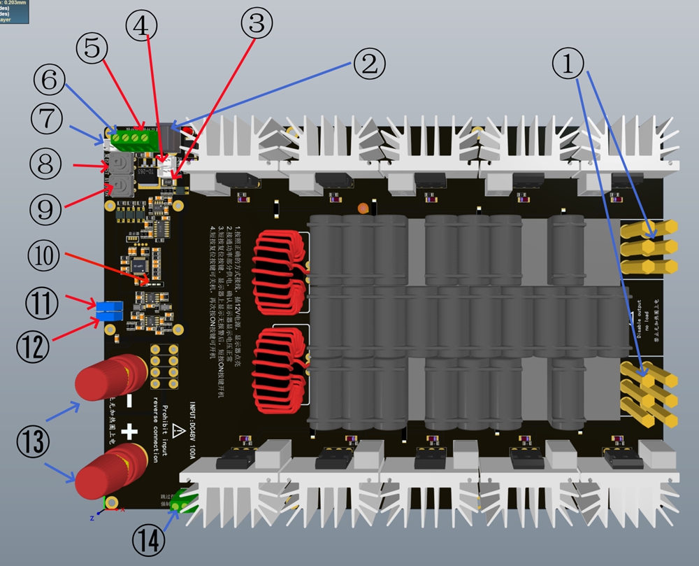
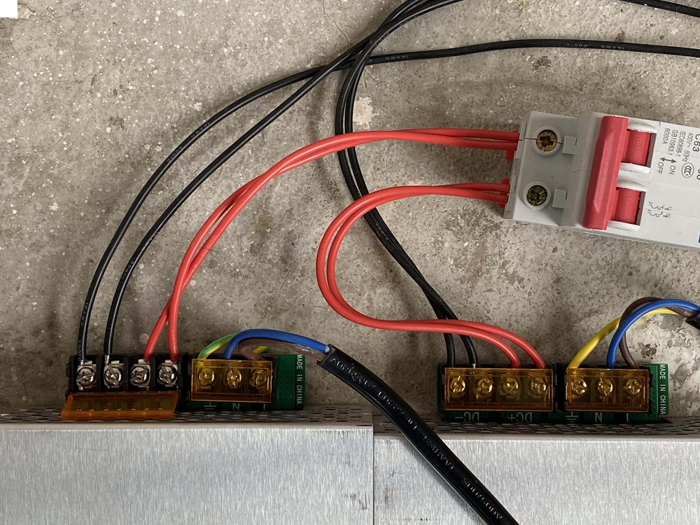
① Heating Coil Output Interfaces (must be correctly installed according to the wiring diagram)
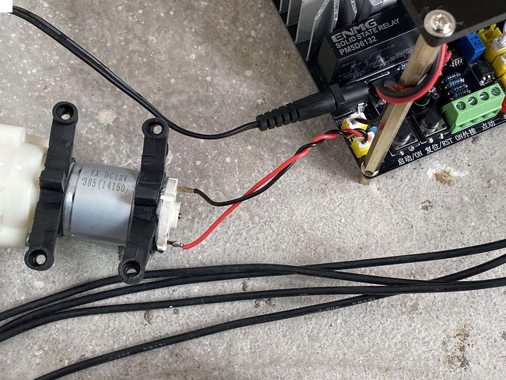
② DC 12V 2A Power Input Interface
③ Water Pump Interface (must use the matching water pump)
④ Onboard Fan Interface
⑤ Reset External Connection (same function as ⑧, reserved for remote control)
⑥ ON External Connection (same function as ⑨, reserved for remote control)
⑦ Jog External Connection (for external foot switch, etc.; press to power on, release to power off)
⑧ Reset Button (to turn off heating or clear alarms)
⑨ ON Button (start heating)
⑩ Water Cooling Alarm Switch Selector (can disable onboard water cooling alarm when using an external water pump)
⑪ OCP Adjustment Potentiometer
⑫ UVP Adjustment Potentiometer
⑬ DC 48V Power Input Interface
⑭ Forced Start Interface (connect a switch to bypass alarms and force startup; see instructions for details)
Operating Instructions:
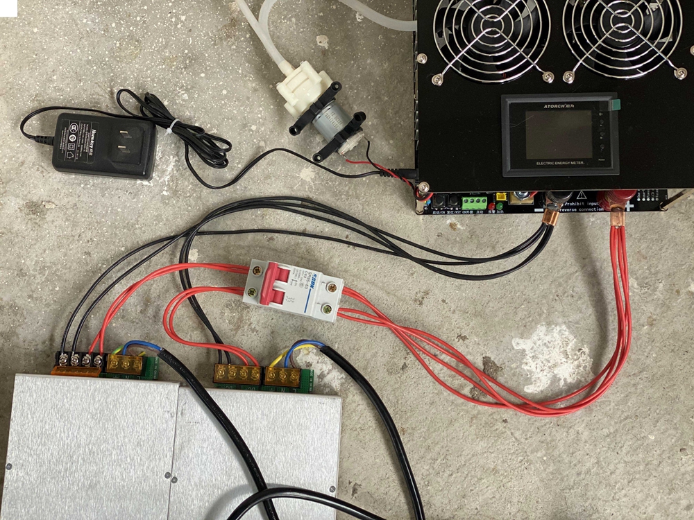
1. Connect all wiring according to the wiring diagram. Carefully inspect all connections and ensure no mistakes. (The fans and support pillars are shipped separately from the mainboard and must be properly assembled according to the wiring diagram.)
2. First, plug the 12V 2A power supply into an AC 110V–220V outlet. Check whether the water pump and fans are operating correctly, and whether the display screen lights up.
3. If the water pump, fans, and display are working normally, plug the DC 48V power supply into an AC 220V outlet. Wait a few seconds, then turn on the air switch (this switch is optional). Observe whether the voltage displayed on the mainboard is around 48V.
4. If the voltage is displayed correctly, press the reset button to clear the startup alarm. Once the display shows no alarms, press the ON button to begin heating. The green indicator light will illuminate, and if current is shown on the display with a status of ON, heating is active.
5. To stop heating, press the Reset button. The green indicator light will turn off, the power meter current will drop to zero, and the display status will show OFF.
6. This heating board includes overload protection and water shortage protection. If the water pump malfunctions or there is insufficient water, the system will automatically shut off heating. The display will indicate Water Shortage. In the event of over-current or under-voltage, the display will show Over-current or Under-voltage respectively.
7. The forced start switch at position ⑭ can be connected to force startup in cases where the alarm system fails or the control circuit is damaged. When using this function, always monitor the water cooling system. If water flow is interrupted during operation, the board may be damaged.
8. If the red indicator light turns on and heating stops during use, identify the fault according to the alarm type shown on the display and troubleshoot accordingly.
9. If heating stops due to current, voltage, or power alarms, after clearing the alarm you must manually reset by pressing the reset button before restarting heating.
10. Terminals ⑤, ⑥, and ⑦ need to be connected to self-reset switches (such as foot switches). Pressing the self-reset switch will cause it to automatically spring back.
11. Maximum current and minimum input voltage alarm levels can be set via potentiometers ⑪ and ⑫. After powering on with 12V DC, these potentiometers can be adjusted while the display shows real-time values. OCP means over-current point and UVP means under-voltage point.
Wiring Diagram (For Reference Only):