| Quantity | 3+ units | 10+ units | 30+ units | 50+ units | More |
|---|---|---|---|---|---|
| Price /Unit | $8.26 | $8.09 | $7.84 | $7.50 | Contact US |
 G1009 10-inch Embedded HD Industrial Monitor 1024x768 Hook Mount TFT Display with BNC/VGA/AV/HDMI-compatible Ports
$109.57
G1009 10-inch Embedded HD Industrial Monitor 1024x768 Hook Mount TFT Display with BNC/VGA/AV/HDMI-compatible Ports
$109.57
 G121SN01 V3 Color Active Matrix LCD Display Panel Designed for Various Industrial Applications
$88.42
G121SN01 V3 Color Active Matrix LCD Display Panel Designed for Various Industrial Applications
$88.42
 RTU-307D NET-07D 8AI-8DI-8DO Data Acquisition Module IO Module (RS485+RS232) for Industrial Use
$76.89
RTU-307D NET-07D 8AI-8DI-8DO Data Acquisition Module IO Module (RS485+RS232) for Industrial Use
$76.89
5A 120W DC Motor Speed Controller Regulator CW CCW Automatic Control of Host Computer Process
Applications:
Suitable for DC motor testing, programmable control of DC motor (up to 6 state cycles, free loading), which is convenient for tooling or other control.
Please read user manual before using. Download the manual and PC software https://pan.baidu.com/s/1JgmnF87P5LAp_5KTEP5nAQ
Attention:
1. Power and drive products are power products. Please read the manual or product description carefully before using.
2. Reverse connection of power supply is not allowed, otherwise it will be damaged.
3. The maximum module current is 5A, 120W. When the module is extremely hot, please derate it to avoid overheating and burning.
Features:
- It has four modes, namely manual control, automatic control, host computer control and serial port control.
- With PC software. You can control motor or set automatic control parameters through the host computer software. Setting parameters will not be lost after power off.
- Control circuit and drive circuit are optocoupler isolated, which has strong anti-interference ability.
- Motor running status indicators are with different colors, indicating current running status.
- A rotary potentiometer with a switch can be used as a power switch and for convenient speed regulation. Frequency adjustment adopts dip switch. It is simple and convenient to operate.
- External port is reserved for external control switch and TTL communications. Software loads the module after setting program.
- Operating status can be quickly switched without noise, with stepless speed change.
Specifications:
- Input voltage range: DC5V-26V. (No anti-reverse connection protection)
- Drive motor current: maximum 5A, instantaneous maximum current 50A. (Without short-circuit protection, it is recommended to connect 6A fuse in series at output end)
- Standby current: <5mA.
- Speed adjustment range: Adjusted by rotary potentiometer. Stepless speed adjustment 0% -100%
- Frequency Range:
Manual control: 8 levels of 300Hz-10KHz
Automatic, software, serial port control: 300Hz-10KHz can be adjusted arbitrarily
Attention: The lower the selected frequency, the greater the fluctuations caused by input power supply.
- Serial communications: TTL level. (Do not connect directly to computer's 232 interface)
- Working temperature: -40℃ to 85℃
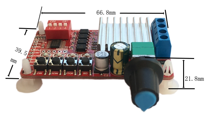
- Size: 67 * 39 * 15mm (L*W*H)
- Mounting hole: 4mm in diameter
- Weight: 30g
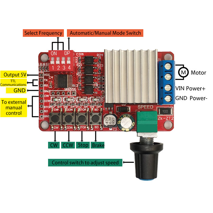
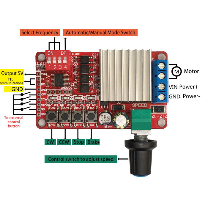
Signal Interfaces Introduction:
VCC: 5V power output port, which can supply power to customers' 485 to TTL modules, USB to TTL modules, etc .. Power supply current is 20mA.
TX, RX: TTL communications interface connects to host computer software.
CW, CCW, STOP, SD: CW, CCW, stop, and brake buttons lead out. When the port is floating, it is high-level 5V, which can be connected to a button to GND, and it is equivalent to the keys on the module, or connected to 5V MCU IO control, low-level trigger (to ensure reliable triggering, low-level time >100ms. Set high after triggering. It can also be always low. But before the next action, you must raise the port high. When dip switch 4 is set to ON position, it is in automatic control mode, and the key or the port is invalid).
Functions:
The module has four motor control modes: manual mode, automatic mode, host computer control mode, and serial port control mode.
1. Manual Mode:
When dip switch 4 is turned downwards, it is in manual mode. Please make sure that the serial port is not connected. Dip switch 1, 2, and 3 select the PWM frequency of drive output. There are eight levels in the range of 300Hz-10KHz. There is a prompt message on the back of the module.
After connecting power supply and motor, turn potentiometer clockwise to turn on power switch. It is in stopping mode. Press CW, CCW, stop, and brake buttons to switch to the corresponding state, and the corresponding status indicator is always on. Turn the potentiometer clockwise to accelerate or counterclockwise to decelerate.
Attention: External manual control terminal has manual control function.
2. Automatic Mode:
Turn dip switch 4 upwards to switch to automatic mode. In this mode, it will run automatically according to loaded parameters. Corresponding parameter conditions can be read and changed by host computer software. The address of drive module can also be changed here. Information is not lost when it is power off. Establish a connection before setting parameters: Select serial port number, click 【Open】 button, and click [Read parameter] button.
Attention: When setting auto mode parameters, please click【Read Parameters】button first.
- Motor speed, motor control frequency, number of cycles, cycle conditions, and module address changes in this mode are set by software.
- Click 【Read Parameters】 to read out the module address automatically. If you need to change it, input a value from 0 to 255 in the box.
- Start time and stop time cannot be changed.
- Motor speed can be set from 0% to 100%. Frequency 300Hz-10Khz can be set.
- Number of cycles is 0-99 times. Where 0 represents infinite loop, 1-99 corresponds to loop 1-99 times.
- There are 6 conditions to choose. Each condition has three states: CW, CCW, and stop. Time range can be set in the range of 0-99999 seconds.
- After setting, click 【Write Parameters】button at the top left of the software, and the module will automatically run according to the set number of cycles, running speed, frequency and conditions.
- Module default values: address 0, start time 200ms, stop time 200ms, motor speed 50%, frequency 1KHz, cycle number 0 (infinite). Default automatic control condition is CW for 10s and stop for 1s, CCW for 10s and stop for 1s, and then cycle.
3.Software Control Mode:
After the module is connected to host software (open the software, select serial port number, and click【Open] button】, select 【Software Control】through the status box on the panel.
Select 【Auto Control Manual Control】 to exit software control mode. Automatic control mode or manual control mode depends on dip switch 4.
When software control mode is selected, the module will be controlled by host computer software and will no longer be controlled by manual mode or automatic mode. In software control panel:
When address is 0, all modules can be controlled. When the address is 1-255, only the module at this address can be controlled.
In this mode, the module will run according to the speed, frequency and operating status on the panel for real-time control.
Attention: You can exit software control mode only by clicking【Automatic Control】button on host computer software, or by powering on the module again.
4.Serial Control Mode:
Connect with motor control board through TTL serial port. Send specific commands to control motor's working frequency, speed (duty cycle), CW, CCW, stop, brake and other functions.
Serial port assistant or client serial port parameter setting: baud rate 9600, parity bit NONE, data bit 8, stop bit 1.
Operation commands of serial control mode:
Addr: module address. It is 0 by default.
State: the status of control motor. 0- is for CW. 1- is for CCW. 2- is for stop. 3- is for brake. When it is bigger than 3, it is stopping.
Speed: 0 ~ 7 bits are the high eight bits, and the 8 ~ 15 bits are the low eight bits. The range is 0-100. When the value is greater than 100, it is treated as 100.
Frequency: 0 ~ 7 bits are the high eight bits, and the 8 ~ 15 bits are the low eight bits. The range is 300Hz-10000Hz. When it is less than 300Hz, it is processed at 300Hz. If it is greater than 10000Hz, it will be treated as 10000Hz. The last digit is the BCC XOR check code.
When data format is correct, the module receives it correctly and returns the same data. When receiving an error, tit will return FF FF FF error code.
For example,
Operation command: E0 01 00 00 32 03 20 F0
The module with control address 1 is running clockwise at a frequency of 800Hz and 50% speed.
Return data:E0 01 00 00 32 00 03 20 F0
Attention: When the address in sent command is 0, all connected modules can be operated.
Command to exit serial operation mode: E0 E0 E0
Module returns data: E0 E0 E0
Attention: You must send an exit command after serial port operation, otherwise it will stay in serial port operation mode and cannot return to manual mode or automatic mode.
Note: Electronic knowledge is highly recommended. Please read the description carefully before use. The product is not designed for medical, lifesaving, and life support purposes, and cannot be used in hazardous locations such as coal mine oil depots.
Package Included:
- 1 x DC Motor Speed Controller