| Quantity | 3+ units | 10+ units | 30+ units | 50+ units | More |
|---|---|---|---|---|---|
| Price /Unit | $14.01 | $13.73 | $13.30 | $12.73 | Contact US |
 0-10V/0-25mA 4-Channel Current Voltage Signal Generator Brightness Adjustable LED Signal Collector with 35MM DIN-Rail Base
$20.52
0-10V/0-25mA 4-Channel Current Voltage Signal Generator Brightness Adjustable LED Signal Collector with 35MM DIN-Rail Base
$20.52
 0-10V/0-25mA 4-Channel Current Voltage Signal Generator Module Brightness Adjustable LED Signal Collector
$18.57
0-10V/0-25mA 4-Channel Current Voltage Signal Generator Module Brightness Adjustable LED Signal Collector
$18.57
 Automobile Crank Shaft Synchronization Signal Simulator Module 6-Channel Output Signal Generator Module with LED Display
$64.45
Automobile Crank Shaft Synchronization Signal Simulator Module 6-Channel Output Signal Generator Module with LED Display
$64.45
Product Description:
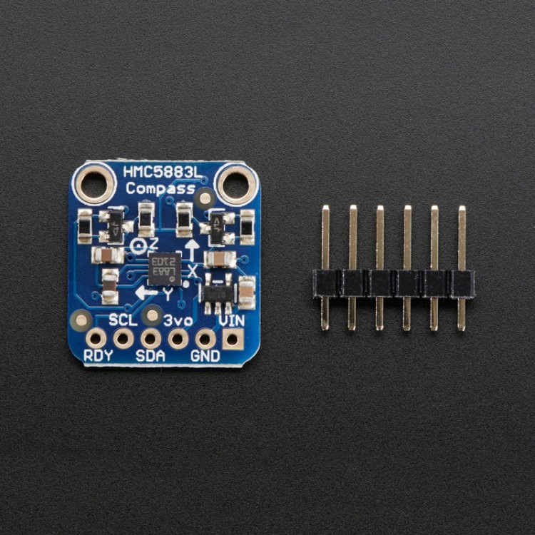
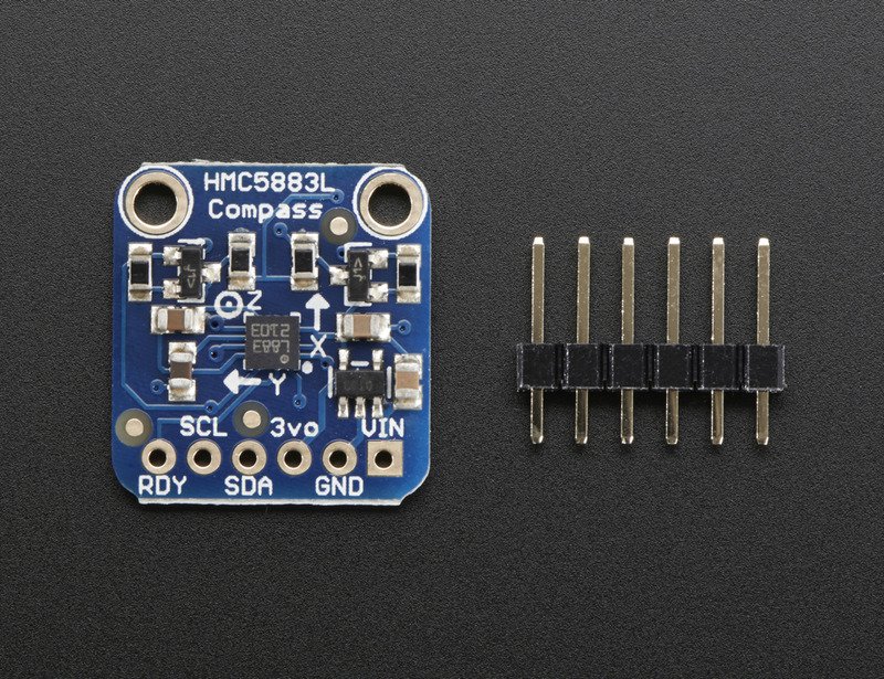
- He told you "Go West, young maker!" - but you don't know which way is West! Ah, if only you had this triple-axis magnetometer compass module. A magnetometer can sense where the strongest magnetic force is coming from, generally used to detect magnetic north.
- We based this breakout on a popular and well loved magnetometer, the HMC5883L. This compact sensor uses I2C to communicate and its very easy to use. Since it's a 3.3V max chip, we added circuitry to make it 5V-safe logic and power, for easy use with either 3 or 5V microcomtrollers. Simply connect VCC to +3-5V and ground to ground. Then read data from the I2C clock and data pins. There's also a Data Ready pin you can use to speed up reads
- This is the same magnetometer sensor that is inside the LSM303. So if you want an accelerometer as well as a magnetometer, check out the LSM303 - it has basically this sensor + a nice digital 3-axis accelerometer!
Specifications:
- I2C interface
- 1-2 degree heading accuracy
- Integrated 12-bit ADC
- 160Hz max data rate
- Range of -8 to +8 Gauss
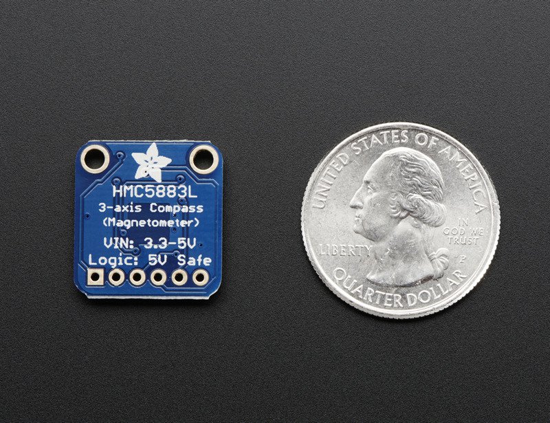
- Panel dimension:16mm*18mm
- Power voltage:3.3V/5V
- Pin distance:2.54mm(100mil)
- Size:3x3x0.9mm
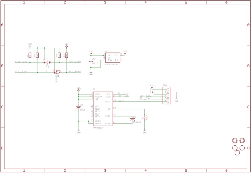
Pinouts:
This is a fairly simple breakout. The sensor itself is super tiny and in the middle of the PCB. We have all the useful pins broken out in to a 0.1" spaced header at the bottom
- VIN - this is the power in pin, give it 3-5VDC. It is reverse-polarity protected. Use the same voltage as you do for the controlling microcontroller's logic. For an Arduino, 5V is best.
- GND - this is the common power and data ground pin
- 3vo - This is the 3.3V output from the onboard regulator. It will be at 3.3V and you can grab up to 100mA from this to power other items
- SDA and SCL - these are the I2C data and clock pins used to send and receive data from the module to your microcontroller. There are 10K pullups on these pins to the VIN pin. You can connect these pins to 5V I2C lines, there are level shifters on board to safely bring the pins down to 3V
- RDY - this it the 'data ready' pin output. If you want to stream data at high speed (higher than 100 times a second) you may want to listen to this pin for when data is ready to be read. Check the datasheet for more details about using the RDY pin, we don't use it because we don't read that fast!
Assembly:Assembly is really easy, you can use straight or 'right-angle' style headers to attach to the PCB. We'll be using the plain straight headers includedThe board comes with all surface-mount components pre-soldered. The included header strip can be soldered on for convenient use on a breadboard or with 0.1" connectors. You can also skip this step and solder on wires.
Prepare the header strip:
- Cut the strip to length if necessary. It will be easier to solder if you insert it into a breadboard - long pins down
- Add the breakout board:
Place the breakout board over the pins so that the short pins poke through the breakout pads
- And Solder!
Be sure to solder all 5 pins for reliable electrical contact.
- You're done! Check your solder joints visually and continue onto the next steps
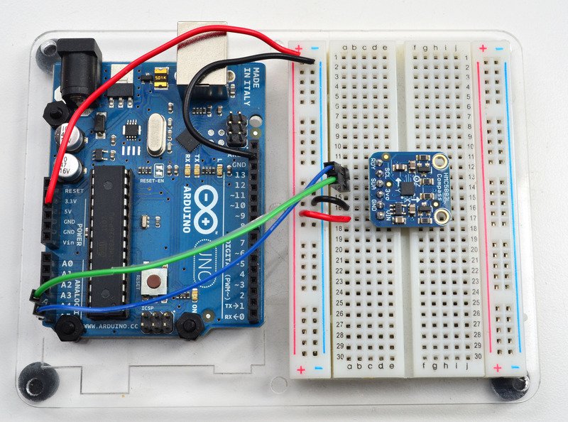
Wiring and Test:
- This 3-axis magnetometer breakout is thankfully very easy to use. It only requires 2 power pins and 2 data pins.
We'll be demoing it with an Arduino but any other microcontroller can be used if you are willing to port the I2C code. We suggest using an Arduino to start since its guaranteed to work.
- Connect VIN to 5V pin on the Arduino. If you have a 3V logic Arduino, connect VIN to 3V instead
- Connect GND to the ground pin on the Arduino
- Connect the SDA pin on the breakout to the I2C data SDA pin on your Arduino. On an UNO & '328 based Arduino, this is also known as A4, on a Mega it is also known as digital 20 and on a Leonardo/Micro, digital 2
- Connect the SCL pin on the breakout to the I2C clock SCL pin on your Arduino. On an UNO & '328 based Arduino, this is also known as A5, on a Mega it is also known as digital 21 and on a Leonardo/Micro, digital 3
The HMC5883L has a fixed I2C address, you can only connect one sensor per microcontroller!
Package List:
- 1 x HMC5883L Magnetometer Board
- 1 x Drive program
- 1 x Schematic diagram
- 1 x Chip datasheet
- 1 x User manual