| Quantity | 3+ units | 10+ units | 30+ units | 50+ units | More |
|---|---|---|---|---|---|
| Price /Unit | $81.17 | $79.52 | $77.03 | $73.72 | Contact US |
 FUZRR ES3000P Multifunctional Micro-controller 3-Wire Ground Resistance Tester 0-20Kohms High Precision Earth Resistance Tester
$275.47
FUZRR ES3000P Multifunctional Micro-controller 3-Wire Ground Resistance Tester 0-20Kohms High Precision Earth Resistance Tester
$275.47
 150W Multifunctional Bluetooth Battery Capacity Tester CC/CR/CP/CV/PT/BRT Intelligent DC Programmable Electronic Load
$59.21
150W Multifunctional Bluetooth Battery Capacity Tester CC/CR/CP/CV/PT/BRT Intelligent DC Programmable Electronic Load
$59.21
 FUZRR ES3090E 220A Loop Resistance Tester Micro-ohmmeter for High Voltage Switch Contact Resistance Measurement
$1,466.23
FUZRR ES3090E 220A Loop Resistance Tester Micro-ohmmeter for High Voltage Switch Contact Resistance Measurement
$1,466.23
ADF4351 35MHz-4.4GHz PLL Signal Source Frequency Synthesizer with Cavity 30DB Dynamic Range
Description:
-Smart signal generator is a wideband and practical handheld simple RF signal source, which is displayed on a computer host computer and integrates a high-performance frequency synthesizer and amplitude control unit (already calibrated) to ensure high performance, small size, low power consumption and high Cost-effective.
-Smart signal generator uses a standard USB 2.0 connector (TYPE-C) for device communication, suitable for indoor, outdoor and even outdoor use in different environments; because the device is light and compact and has its own display, it is particularly suitable for carrying around.
-The frequency range included in the smart signal generator is ADF4351 (37.5MHz-4.4GHz); minimum frequency step is 1KHz; with amplitude adjustment function, the maximum output amplitude in the range of LF to 2.5GHz is + 15dBm,and the maximum output amplitude in the 2.5GHz to 4.4GHz range is 5dBm (refer to the actual measured value for details).
Specification:
1. Net weight of host: 90g (using CNC aluminum alloy CNC shell)
2. USB power supply current 300mA
3. Adopt PL2303SA serial port to USB chip for communication, and the driver wizard can be installed automatically when installing the driver
4.Functions: the left SMA port, the default delivery mode is 10MHz, plus or minus 0.1ppm temperature compensation clock source output, can also be configured as an external clock input mode (need to contact the owner to modify); the SMA port on the right can be set as a point-frequency RF source / sweep source by pressing the button / host software, and the amplitude can be controlled numerically.
5. Size: length, width and height: 68 * 48 * 17mm (not including protruding SMA interface)
6. With OLED and buttons, it can be run offline or controlled by the host computer. It has power-off storage and can store the value of the last power-off.
RF Signal Source Port Index:
1. Frequency range of output signal: ADF4351(35MHz-4.4GHz)
2. Signal amplitude range: -20dBm to + 15dBm (LF-2.5GHz range) has passed the calibration; -15dBm to + 5dBm (2.5G-4.4GHz range) has been calibrated. (Each frequency band exceeds the above setting range, the LCD display value is not calibrated)
3. Frequency resolution: 1KHZ
4. Frequency stability and accuracy (typical value): ± 0.1ppm
5. Harmonic 17dBc (@ 1GHz)
6. Phase noise: phase noise= -104.00dBm/Hz@1GHz 100KHz
Harmonic and Phase Noise Indicators of RF Signal Source Port:
1. Harmonic analysis, output signal 1GHz, amplitude 0dBm output, second harmonic is 16.61dBc at 2GHz, third harmonic is 17.68dBc at 3GHz.
2. Phase noise analysis, when the output signal is 1GHz and the amplitude is 0dBm.
RF Signal Source Flatness Test:
1. The RF signal source is set to LF-4400MHz, frequency sweep output, step 100K, frequency sweep time 10ms, power is set to maximum output; the spectrum analyzer uses the maximum hold mode.
2. The RF signal source is set to LF-4400MHz, frequency sweep output, step 100K, frequency sweep time 10ms, power is set to + 5dBm output; the spectrum analyzer uses the maximum hold mode.
3. The RF signal source is set to LF-4400MHz, frequency sweep output, step 100K, frequency sweep time 10ms, power is set to 0dBm output; the spectrum analyzer uses the maximum hold mode.
4. The RF signal source is set to LF-4400MHz, frequency sweep output, step 100K, frequency sweep time 10ms, power is set to -10dBm output; the spectrum analyzer is set to the maximum hold mode.
5. The RF signal source is set to LF-4400MHz, frequency sweep output, step 100K, frequency sweep time 10ms, power is set to -15dBm output; the spectrum analyzer uses the maximum hold mode.
Operation Manual:
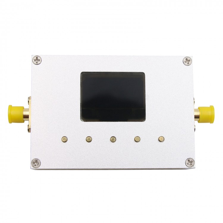
1. Hardware Picture
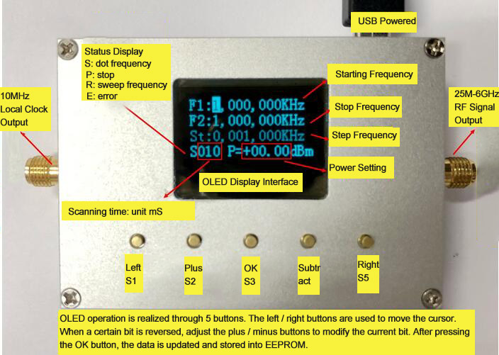
2. Hardware Panel Operation Instructions
Refer to the above picture for a brief explanation:
1) Power supply: Connect the power supply (computer) through TYPE-C
2) Power switch: next to the USB, switch to the left to turn on, switch to the right to turn off.
3) Press the "OK S3" key to start the frequency sweep and stop the frequency sweep.
4) Press S1 to change the cursor position(move to the left);
Press S5 to change the cursor position (move to the right);
Press S2 to change the data of cursor position (plus);
Press S4 to change the data of the cursor position (subtract);
After entering the system, the cursor indicates the selected digit. At this time, the up and down buttons can be used to modify the value of the selected digit. When the cursor is at the last digit (or first digit) of the selected item, press the right button (or left button) to switch the selected item. After setting the parameters, press the middle OK key to make the setting effective.
OLED operation is realized through 5 buttons. The left / right buttons are used to move the cursor. When a certain bit is reversed, adjust the plus / minus buttons to modify the current bit. After pressing the OK button, the data is updated and stored into EEPROM.
PC Software Operating Instructions:
1) Connect the hardware first, then turn on the host computer, set the baud rate to 115200, and find the corresponding serial port.
Serial port number query method: right-click "My Computer" and select Manage. Open the computer management, open the device manager, click "port (COM and LPT)", you can view the port number.
Serial driver: PL2303SAusb driver collection xpwin7.rar, install this driver.
Software Interface Diagram:
1) Open the "RF signal source control software" software, pop up the host computer interface, note that "static.ini" is not a virus file, it is used to save the value set by the host computer, and the "RF signal source control software" file In the same folder.
2) The host computer interface can set the start frequency, end frequency, frequency sweep step, step time, power setting, set all parameters with one key, run the frequency sweep, and stop the frequency sweep. Note that when the start frequency is the same as the end frequency, it is the point frequency output, or the sweep frequency is in the stopped state, and the output point frequency signal frequency is the start frequency value.
Package Included:
1 x Signal Source