AK4137 I2S/DSD Sample Rate Converter for PCM/DSD Inter-conversion DOP Input (Low Frequency Version)
Description:AK4137 supports PCM to PCM (convertible sample
rate and data format), DSD to DSD (convert DSD sample rate), PCM to DSD,
DSD to PCM, DOP to PCM, and DOP to DSD.
Optional Versions:- Standard version: crystal oscillator 22.5792M 24.576M
- Low frequency version: crystal oscillator 11.2896M 12.288M
- 768K version: crystal oscillator 2.5972M 49.152M
The sample rate of the output function supported by each version is as follows: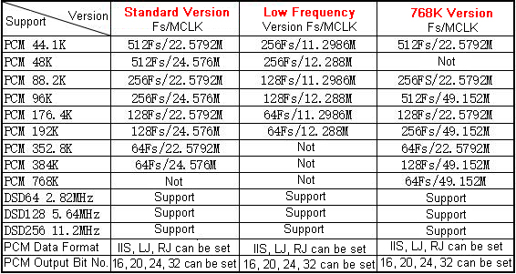 Note:
Note:
- The following details are based on the Standard Version.
Input Signal Range of this Board:PCM
mode can input I2S (16-32bit I2S format is also called format for
Philips), LJ (left-aligned format 16-32bit), RJ24 (right-aligned format
24bit, format for Sony), RJ32 (right-aligned format 32bit, format for
Sony). Due to the design of the chip manufacturer, signal inputs with
right-aligned formats (for Sony) lower than 24 bit are not supported.
DSD mode can input DSD64 DSD128 DSD256. and DOP data (DOP data is to be
entered in PCM mode).
Output Signal Range of this Board:-
PCM mode can output I2S, LJ (left-aligned format) and RJ (right-aligned
format) formats. All three formats can output 16bit, 20bit, 24bit, and
32bit data at 44.1K/48K/88.2K/96K/176.4K/192K/352.8K 384K sample rates,
as well as slave mode. DSD mode can output DSD64/DSD128/DSD256.
-
Note: The input PCM signal below 44.1K will not convert to DSD, nor will
it be converted to a higher sample rate of the PCM. When the input PCM
signal is lower than 176.4K, it can output DSD64 DSD128, but cannot
output DSD256.
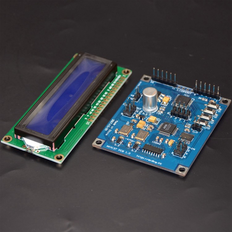
Board Interface Description:- The POW
interface is a power input interface, which do not reverse connection
for DC power supply, and the limit voltage is DC 4.6-5.5V (this is only
the limit voltage range of the AK4137 board; The voltage range of the
display is subject to the display screen used). The I2S/DSD-OUT
interface is the I2S/DSD data output interface; I2S/DSD-IN is the
I2S/DSD data input interface; D/P is the interface for manual control of
PCM/DSD input mode (PCM/DSD input mode can also be controlled through 1
pin of the data input port); The K port is a special function
interface; LCDPORT is the display interface (display connection method:
pin 1 of the PCB board is connected to pin 1 of the display, the pin 2
of the board is connected to the pin 2 of the display and so on, the
middle four pins without pins are not connected).
- Note: When using I2S/DSD-IN interface pin 1 to control the input mode, disconnect the D/P interface.
-
There are 4 buttons on the board to set the board (see below for the
setting method), in addition to the mute function, other functions set
by the button support power-off memory, that is, the board still works
according to the last set mode when the next time it is turned on.
-
I2S/DSD-IN interface pin definition: pin 1 is DSD enable input (also
called DSDON or DSDOE), pin 2 is GND, pin 3 is DATA/DSDL input, pin 4 is
BCK/DCLK input, pin 5 is empty pin no connection, and pin 6 is
LRCK/DSDR input. This board input interface does not require an input
MCLK to work.
- I2S/DSD-OUT interface pin definition: pin 1 is DSD
enable output (also called DSDON or DSDOE), pin 2 is GND, pin 3 is
DATA/DSDL output, pin 4 is BCK/DCLK output, pin 5 is MCLK output, and
pin 6 is LRCK/DSDR output. Pin 1 outputs low level when outputing PCM
mode, and pin 1 outputs high level when outputting DSD mode.
Detailed Use Method:Connect
the display screen, etc., turn on the power, connect the POW interface
to the 5.0V DC power supply, and the limit voltage is DC 4.6-5.5V (this
is the limit voltage range of the AK4137 board; the voltage of the
display screen is subject to the display screen used). Reverse
connection is not allowed.
Input Setting:
- Set signal input
mode: first determine the input signal mode, DSD or PCM (I2S), which can
be set via D/P interface. The short-circuited D/P interface input
signal mode operates in PCM (I2S) mode, and the disconnected D/P
interface input mode works in DSD mode. The input mode can also be
controlled through I2S/DSD-IN interface pin 1. When I2S/DSD-IN interface
pin 1 is inputting low voltage, it is in PCM input mode, and when the
input level is high, it is in DSD input mode. It should be noted that
when using I2S/DSD-IN interface pin 1 to control the input mode, the D/P
interface must be disconnected (it cannot be short-circuited or it can
only work in PCM mode; Short-circuiting may also cause damage to the
equipment providing the DSDON/DSDOE signal). When you need to input a
DOP signal, you must also configure the input interface to PCM mode.
Set Signal Input Format:
-
In PCM input mode, the user can switch the format of the input data by
pressing and holding button 1. Each long press of button 1 corresponds
to change the format of an input signal, and the input format is
displayed correspondingly behind the first line of the letter "I" of the
display, with power-off memory function. Input formats include I2S, LJ,
RJ24, RJ32, DOP, and loop switching. In DSD input mode, you can switch
the input DSD sample rate by long-pressing button 2 and the
corresponding display will be displayed after the first line of the
letter "I" with power-off memory. DSD inputs include DSD64, DSD128,
DSD256, and cyclic switching. It is also possible to switch the input
DSD sample rate via K ports K1 and K2 (see table below). It should be
noted that when switching the input DSD signal by pressing and holding
button 2, the user needs to short-circuit K1 and K2 (let K1 and K2 all
be short-circuited, otherwise K1 and K2 will be used to configure the
sampling rate of the DSD input). K1 and K2 can automatically switch the
DSD sampling rate of the input when used with interface for Amanero (K1
is connected to pin 17 of the interface for Amanero, and K2 is connected
to pin 18 of the interface for Amanero).
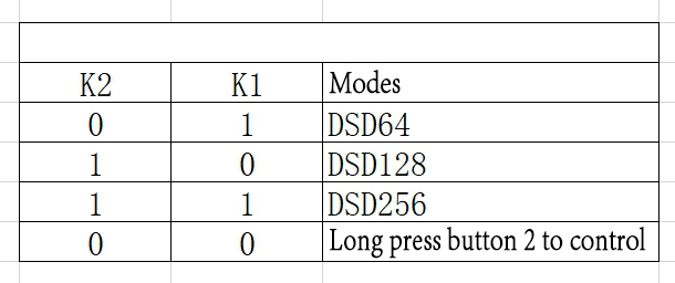
Attention: 0 is input low voltage (0V), 1 is input high voltage (3.3V).
Output Setting:
-
Set output format: Switch the format of the output signal by short
pressing button 1. The formats that can be set include I2S, LJ
(left-aligned), RJ (right-aligned), DSD64, DSD128, DSD256 and cyclic
switching, with power-off memory function and the related display on the
second line of the screen.
- Setting the sampling rate of PCM output
mode (this function is valid for PCM output mode; the output sampling
rate of DSD is switched by short pressing button 1): The sampling rate
of the output signal is switched by short pressing button 2. The
settable sample rates include 44.1K, 48K, 88.2K, 96K, 176.4K, 192K,
352.8K, 384K, SLA (slave slave mode output) and cyclic switching, with
power-off memory and related display on the second line of the screen.
-
Setting the number of bits for PCM output mode (available for all PCM
data formats): The number of bits for the output signal can be switched
by short pressing button 3. The number of bits that can be set includes
16bit, 20bit, 24nit, 32bit (other bits are not supported) and cyclic
switching, with power-off memory and related display on the second line
of the screen.
Other Settings:
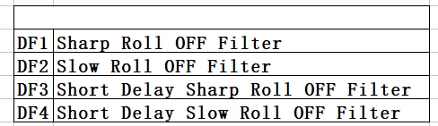
- Digital Filter Settings:
Change the digital filter mode by pressing and holding button 3. This
setting has power-off memory and digital filter mode will be displayed
in the second half of the first line of the screen. The contents
displayed are DF1, DF2, DF3, DF4, which correspond to the filter modes
in the table below.
-
Jitter Settings (add jitter to the signal): set the jitter switch by
long-pressing button 4, and turn on the jitter function when the last
two digits of the second line of the screen display "DT" after
long-pressing button 4, and turn off the jitter after the last two
digits of the second row of the screen display "DT" disappears after
long-pressing button 4. This function comes with power-off memory.
-
Mute Setting: Press button 4 shortly, and when the last two digits of
the first row of the screen display "MT", the board is in silent mode.
After pressing button 4 again, the "MT" disappears to mean that it is
not in mute mode and the audio can play normally. This feature does not
have power-off memory. When the system is turned back on, the mute
function is canceled.
Button Functions:- Button 1:
Press and hold this button to switch the PCM input format (PCM input
mode is valid); Press this button shortly to switch the output mode.
-
Button 2: Press and hold this button to change the DSD input sampling
rate (DSD input mode is valid); Press this button briefly to change the
PCM output sample rate (PCM output mode is active).
- Button 3: Press
and hold this button to switch the filter mode; Press this button
briefly to change the number of PCM output bits (PCM output mode is
active).
- Button 4: After long pressing this button, the button is a
jitter switch; After pressing this button, the button is the mute
switch.
Electrical Characteristics:- Power supply:
DC5V (AC voltage will cause the board to be damaged) 4.8-5.5V (beyond
this range will cause the board to be damaged or not work properly)
- Input signal supports 3.3V and 5V levels; the output signal is 3.3V
- PCB size: 5.2 x 6.3cm/2 x 2.5"
- Using standard 1602 display
-
Both crystal oscillators on the board are powered by precision LDOs,
and turning off the power of the other crystal oscillator when one of
the oscillators oscillator is working can reduce interference.
- In
addition to K1 and K2, please try not to use other interfaces for K
ports, and consult customer service if you need to use them.
Package Included:- 1 x Board
- 1 x Display
")
")
")
")


")
")
 PCM/DSD Conversion DoP Input + 1602 LCD")


