| Quantity | 3+ units | 10+ units | 30+ units | 50+ units | More |
|---|---|---|---|---|---|
| Price /Unit | $27.44 | $26.88 | $26.04 | $24.92 | Contact US |
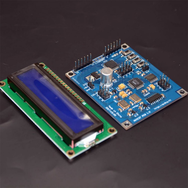
AK4137 I2S/DSD Sample Rate Converter (Standard Version) PCM/DSD Conversion DoP Input + 1602 LCD
Features:
* AK4137 I2S/DSD sample rate converter board
* Supports I2S/DSD conversion
* Supports DoP input
* The AK4137 supports: PCM to PCM (convertible sample rate and data format), DSD to DSD (convertible DSD sample rate), PCM to DSD, DSD to PCM, DoP to PCM, and DoP to DSD
Version Comparison:
* Standard version crystal oscillator configuration: 22.5792MHz, 24.576MHz
* Low-frequency version crystal oscillator configuration: 11.2896MHz, 12.288MHz
* 768K version crystal oscillator configuration: 22.5972MHz, 49.152MHz
The supported output functions, sample rates, and other details of each version are as shown in the following table: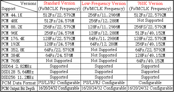
On August 8, 2020, the functions of the K1 and K2 ports were updated, enabling them to work with the Italian interface to automatically switch the input sampling rate to the AK4137 board!
For details, please see the detailed introduction below. All of the following detailed descriptions are based on the Standard Version as a reference.
Input Signal Range of This Board:
In PCM mode, it can accept:
* I²S (I²S format, also called format for Philips, 16–32bit)
* LJ (Left-Justified format, 16–32bit)
* RJ24 (Right-Justified, also called format for Sony, 24bit)
* RJ32 (Right-Justified, also called format for Sony, 32bit)
Due to the chip manufacturer's design, Right-Justified (for Sony) signals below 24bit are not supported. In DSD mode, it can accept: DSD64, DSD128 and DSD256. And it supports DoP data (DoP data must be input in PCM mode).
Output Signal Range of This Board:
In PCM mode, it can output:
* I²S format
* LJ (Left-Justified format)
* RJ (Right-Justified format)
* All three formats can output 16/20/24/32bit data at sample rates: 44.1kHz, 48kHz, 88.2kHz, 96kHz, 176.4kHz, 192kHz, 352.8kHz, 384kHz
It also supports slave mode.
In DSD mode, it can output: DSD64, DSD128, and DSD256.
Note:
* PCM input signals below 44.1kHz cannot be converted to DSD, nor to higher PCM sample rates.
* PCM input signals below 176.4kHz can output DSD64 or DSD128, but cannot output DSD256.
Board Interface Description:
* POW Interface: Power input interface. This board requires DC power and the polarity must not be reversed. The voltage range is DC 4.6–5.5V (this is the limit for the AK4137 board only; the display voltage range depends on the display used).
* I²S/DSD-OUT Interface: I²S/DSD data output interface.
* I²S/DSD-IN Interface: I²S/DSD data input interface.
* D/P Interface: Manual control interface for PCM/DSD input mode (can also be controlled via pin 1 of the data input port).
* K Port: Special function interface.
* LCDPORT: Display interface (connect pin 1 of the board to pin 1 of the display, pin 2 to pin 2, and so on; the four unpinned middle pins are not connected).
Note: When using pin 1 of the I²S/DSD-IN interface to control the input mode, please disconnect the D/P interface.
The board has four buttons for configuration (see the method below). Except for the mute function, all settings made via the buttons are stored in memory, so the board will retain the last configuration after power off and use the same mode on the next startup.
I²S/DSD-IN Interface Pin Definition:
* Pin 1: DSD Enable Input (also called DSDON or DSDOE)
* Pin 2: GND
* Pin 3: DATA/DSDL Input
* Pin 4: BCK/DCLK Input
* Pin 5: Not Connected
* Pin 6: LRCK/DSDR Input
This board's input interface does not require MCLK to operate.
I²S/DSD-OUT Interface Pin Definition:
* Pin 1: DSD Enable Output (also called DSDON or DSDOE)
* Pin 2: GND
* Pin 3: DATA /DSDL Output
* Pin 4: BCK/DCLK Output
* Pin 5: MCLK Output
* Pin 6: LRCK/DSDR Output
When outputting PCM mode, pin 1 outputs low level; when outputting DSD mode, pin 1 outputs high level.
Detailed Usage Instructions:
After connecting the display and other peripherals, turn on the power. Connect the POW interface to a 5.0V DC power supply. The voltage limit is DC 4.6–5.5V (this is only the limit for the AK4137 board; the display's voltage range depends on the display used. Just ensure the voltage is within range and do not reverse polarity).
1. Input-Related Settings:
1.1. Setting the Signal Input Mode:
First, determine whether the input signal is DSD or PCM (I²S). This can be set via the D/P interface:
* Short-circuit the D/P interface → input works in PCM (I²S) mode
* Disconnect the D/P interface → input works in DSD mode
Alternatively, you can use pin 1 of the I²S/DSD-IN interface to control the input mode: When pin 1 of the I²S/DSD-IN interface is low, the board operates in PCM input mode. When it is high, the board operates in DSD input mode. Note: When using pin 1 of the I²S/DSD-IN interface to control the input mode, the D/P interface must be disconnected. Do not short-circuit it, or the board will only work in PCM mode and it may damage the device providing the DSDON/DSDOE signal. To input DoP signals, the input interface must also be set to PCM mode.
1.2. Setting Signal Input Format:
In PCM input mode, long-press Button 1 to switch the input data format. Each long press cycles to the next input format. The current format is displayed after the letter I on the first line of the display. Settings are retained in memory after power off.
Available PCM input formats: I²S, LJ, RJ24, RJ32, DoP, cycling continuously.
In DSD input mode, long-press Button 2 to switch the DSD input sample rate. The current rate is displayed after the letter I on the first line, with memory retention after power off. DSD input options: DSD64, DSD128, DSD256, cycling continuously.
Alternatively, the K ports (K1 and K2) can also be used to switch the DSD input sample rate (see Table 1). Note: When switching DSD signals using Button 2, K1 and K2 must be shorted (all shorted) to allow Button 2 to control the DSD sample rate; otherwise, the board will use the sample rate set by K1/K2. K1 and K2 can automatically switch the DSD input sample rate when paired with the Italian interface (K1 connects to pin 17, K2 connects to pin 18 of the Italian interface).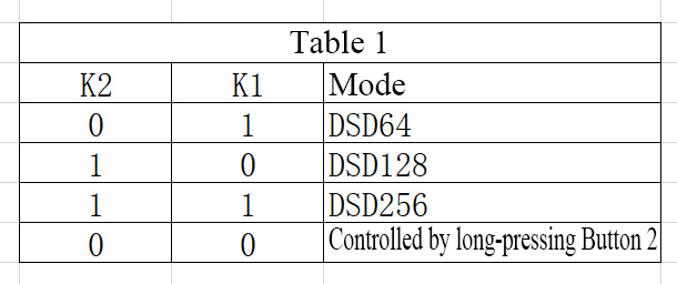
Note: 0 = Input Low Level (0V), 1 = Input High Level (3.3V)
2. Output-Related Settings:
2.1. Setting Output Format:
Short-press Button 1 to switch the output signal format. Available formats include: I²S, LJ (Left-Justified), RJ (Right-Justified), DSD64, DSD128, DSD256. Settings cycle continuously, are retained after power off, and are displayed on the second line of the screen.
2.2. Setting PCM Output Sample Rate):
* This function is effective in PCM output mode. DSD output sample rates are switched using Button 1.
* Short-press Button 2 to switch the output signal sample rate. Available sample rates: 44.1kHz, 48kHz, 88.2kHz, 96kHz, 176.4kHz, 192kHz, 352.8kHz, 384kHz, and SLA (Slave Mode Output).
Settings cycle continuously, are retained after power off, and are displayed on the second line of the screen.
2.3. Setting PCM Output Bit Depth (Applicable to all PCM data formats):
Short-press Button 3 to switch the output bit depth. Available bit depths: 16-bit, 20-bit, 24-bit, 32-bit (other bit depths are not supported). Settings cycle continuously, are retained after power off, and are displayed on the second line of the screen.
3. Other Settings:
3.1. Digital Filter Settings:
Long-press Button 3 to switch the digital filter mode. This setting is retained after power off, and the display shows the mode on the second half of the first line. The display shows DF1, DF2, DF3, DF4, corresponding to the filter modes listed in Table 2.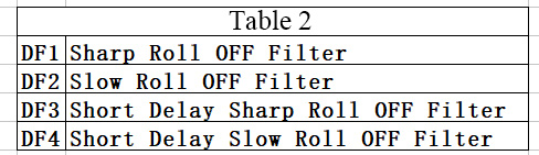
3.2. Jitter Settings (Adding Jitter to the Signal):
Long-press Button 4 to toggle the jitter function. After long-pressing, if the last two characters on the second line of the display show DT, the jitter function is enabled. Long-press again to disable; the DT will disappear from the display. This setting is retained after power off.
3.3. Mute Settings:
Short-press Button 4 to toggle mute. When the last two characters on the first line of the display show MT, mute is enabled. Short-press again to cancel mute and resume normal playback. This setting is not retained after power off; mute will be canceled after restarting.
4. Button Function Table:
* Button 1: Long press to switch PCM input format (effective in PCM input mode); short press to switch output mode.
* Button 2: Long press to switch DSD input sample rate (effective in DSD input mode); short press to switch PCM output sample rate (effective in PCM output mode).
* Button 3: Long press to switch filter mode; short press to switch PCM output bit depth (effective in PCM output mode).
* Button 4: Long press to toggle jitter function; short press to toggle mute function.
Electrical Characteristics:
* Power Supply: DC 5V (connecting AC voltage will damage the board). Voltage range: 4.8–5.5V (exceeding this range may damage the board or prevent normal operation).
* Input Signal Levels: Supports 3.3V and 5V levels
* Output Signal Level: 3.3V
* PCB Dimensions: 5.2cm × 6.3cm
* Display: Standard 1602 LCD
* Both crystal oscillators on the board use precision LDO power supply. When one oscillator is operating, the other's power is turned off to reduce interference.
* K Port: Except for pins 1 and 2 (K1, K2), other pins should not be used without guidance. If you need to use them, please consult customer service.
Attention:
* For brand/copyright protection, all products with displays from our store will show the store logo or website by default when powered on. If you need the display to not show this or to modify the display content, please contact customer service.
* For any information not included in the product description, please consult customer service.
* Due to instability in the electronics market, some components may be out of stock and replaced with other brands, but this will not affect the board's performance. Please make sure that you don't mind before purchasing.
* This product does not provide schematics or related files; only interface definitions are provided (as described in the introduction or marked on the board).
Packing List:
* 1 × SRC Module
* 1 × Display
Packaging Details:
* Weight: 0.15kg
 PCM/DSD Conversion DoP Input + 1602 LCD")
 PCM/DSD Conversion DoP Input + 1602 LCD")
 PCM/DSD Conversion DoP Input + 1602 LCD")


")
")
")


