| Quantity | 3+ units | 10+ units | 30+ units | 50+ units | More |
|---|---|---|---|---|---|
| Price /Unit | $56.87 | $55.71 | $53.97 | $51.65 | Contact US |
 H2MD DC24-120V 6A Engraving Machine CNC Stepper Motor Driver Module Support Phase Dislocation Protection
$45.54
H2MD DC24-120V 6A Engraving Machine CNC Stepper Motor Driver Module Support Phase Dislocation Protection
$45.54
 ZM-3H2080 24V High Performance 3-Phase Stepper Motor Driver Controller AC80-220V for 86-130MM Stepper Motors
$166.32
ZM-3H2080 24V High Performance 3-Phase Stepper Motor Driver Controller AC80-220V for 86-130MM Stepper Motors
$166.32
 ZM-3H2080 12V High Performance 3-Phase Stepper Motor Driver Controller AC80-220V for 86-130MM Stepper Motors
$166.32
ZM-3H2080 12V High Performance 3-Phase Stepper Motor Driver Controller AC80-220V for 86-130MM Stepper Motors
$166.32
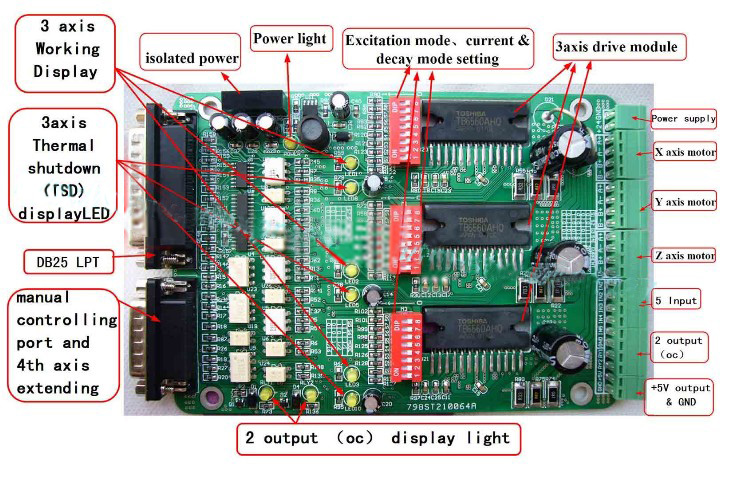
Aluminum Box CNC 3 Axis Stepper Motor Driver Board M335-T3 3 axis CNC Motor Driver
Description
- Low noises and low vibration due to the using of the 16 excitation two-phase bipolar stepping motor driver chip TB6560AHQ imported from Japan. The electric circuit is well-designed. All the electric items have been strictly checked to insure the quality.
Specification
- rated voltage: DC12-DC30V;
- Single-chip motor driver for sinusoidal microstep control of stepping motors
- Forward and reverse rotation
- Selectable phase excitation modes (2, 1-2, 2W1-2 and 4W1-2)
- High output current: IOUT = AHQ: 3.5 A (peak)
- Thermal shutdown (TSD)
If you need 36v power pls contact us.
Advantages
- one power only
- The control parts and the driving parts share one power. Users don't need any more power.
- adjustable electric current
- The out-put current can be adjusted according to user's needs.
- well-arranged ports
A: The X port, the Y port and the Z port are connected to one port (3.96mm), which is very convenient for users to arrange the circuitry.
B: The stop signal input-port is connected to one port (3.96mm), which is very convenient for users to arrange the circuitry.
manual-control function
- Users can manually control the drive board through a standard port which has 15 pins
- the 4th axis can be added
Through a standard port which has 15 pins, the 4th axis can be added to the drive board according to users' needs.
- protection of the computer
- By using the isolating power(1000V DC\DC) and the optoelectronic coupler, the drive board are separated from the computer. Such design can protect user's computer in case the board are going abnormal.
- protection of the drive board
- The electric current of the drive board is locked to half of the normal one when no signals are received from the computer, thus the service life of the drive board is assured with less heat.
- good-cooling function
- All the items are fixed in a aluminium box which has good performance of the abstraction of heat to ensure the service life.
5. Ports
5.1 DB25 LPT pin define:
1. the 2nd output control (corresponding circuitry pls see RY2 on the board, for electric relay or PWM OC output control, output current=50mA, voltage=24V)
2 :X axis pulse input
3 :X axis direction setting
4 :Y axis pulse input
5 :Y axis direction setting
6 :Z axis pulse input
7 :Z axis direction setting
8 :extending axis pulse input
9 :extending axis direction setting
10:LPT input signal 1 (corresponding IN1 on the board)
11:LPT input signal 2 (corresponding IN2 on the board)
12:LPT input signal 3 (corresponding IN3 on the board)
13:LPT input signal 4 (corresponding IN4 on the board)
14:NC
15:LPT input signal 5 (corresponding IN5 on the board)
16:all axis enable input
17:the 1st circuitry output control (corresponding circuitry pls see RY1 on the board, for electric relay or PWM OC output control, output current=50mA, voltage=24V)
18:GND
19:GND
20:GND
21:GND
22:GND
23:GND
24:GND
25:GND
5.2 Manual control ports and definition
Input signal=0-5V
1 :X axis pulse input
2 :X axis direction setting
3 :Y axis pulse input
4 :Y axis direction setting
5 :Z axis pulse input
6 :Z axis direction setting
7 :all axis enable input
8 :the 1st circuitry output control (corresponding circuitry pls see RY1, for electric relay or PWM OC output control, output current=50mA, voltage=24V)
9 :extending axis pulse output
10:extending axis direction output
11:extending axis enable output
12:the 1st circuitry input control
13:5V power ,20mA
14:Direct connecting to IN1
15:Power GND
5.3 Power port
Power:12-24V
Current:10A
Pls see the picture for reference.
up: power GND
Down: power 12-24V
5.4 Port for extending
From up to down:
1.IN1
2.IN2
3.IN3
4.IN4
5.IN5
6.GND
7.RY1
8.RY2
9.+5V
10.GND
6. Subdivision surface mode setting
6. Subdivision surface mode setting
|
| S5 | S6 |
| 1 | 1 | 1 |
| 1/2 | 1 | 0 |
| 1/8 | 0 | 0 |
| 1/16 | 0 | 1 |
7. Decay mode setting
|
| S7 | S8 |
| NO DECAY | 1 | 1 |
| SLOW DECAY | 1 | 0 |
| MID DECAY | 0 | 1 |
| FAST DECAY | 0 | 0 |
Notes: if the drive board has abnormal noise under working or locking condition, you can solve the problem by adjusting the decay mode.
8. Current adjusting and default testing
|
| S1 | S2 | S3 | S4 |
| 20%-->20% | 0 | 0 | 1 | 1 |
| 50%-->20% | 0 | 1 | 0 | 1 |
| 75%-->20% | 0 | 0 | 1 | 0 |
| 75%-->50% | 1 | 0 | 0 | 0 |
| 100%-->20% | 0 | 1 | 0 | 0 |
| 100%-->50% | 0 | 0 | 0 | 0 |
Explanation:
EXAMPLE: 75%-->20%
Working Current=3.5A *75%
Pause current=3.5A *20%