| Quantity | 3+ units | 10+ units | 30+ units | 50+ units | More |
|---|---|---|---|---|---|
| Price /Unit | $21.54 | $21.10 | $20.44 | $19.56 | Contact US |
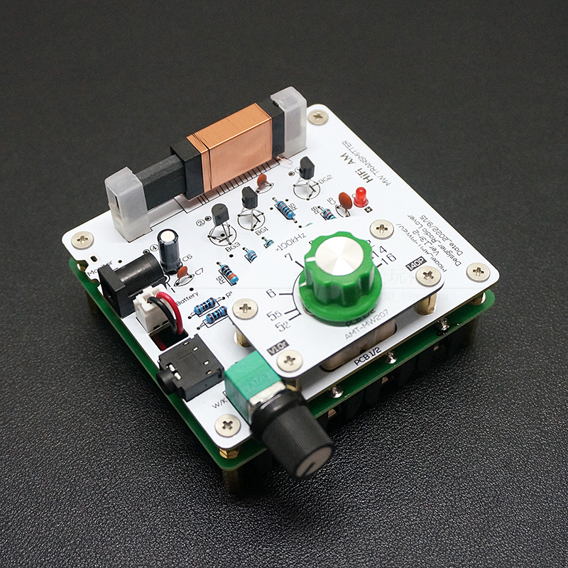
AMT-MW207 Medium Wave Radio Transmitter High Fidelity AM Radio Transmitter DIY Circuit Board 525~1605kHz 6V
Description:
- AMT-MW207 medium wave transmitter is a simple AM signal source suitable for amateur electronics enthusiasts and radio enthusiasts. It uses a magnetic rod to transmit electromagnetic waves without an external antenna. It can be used to test ordinary medium wave radios in places where the radio signal is insufficient. As well as ore radios, it can also be used as an instrument for debugging medium wave radios.
- This kit adopts full discrete circuit, which is especially suitable for students to learn the working principle, practice production and test.
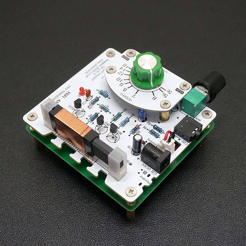
- The variable capacitor uses a double-connected variable capacitor, and the two-connection parallel connection can obtain sufficient capacity.
- Using double-sided circuit, the board base is glass fiber material, the thickness is measured about 1.5~1.6mm, the pad is sprayed with tin, and it can be directly welded without grinding.
- This product has been revised for n times so far (mainly to modify the wiring of the circuit board and the circuit remains unchanged), and it is still in the process of continuous improvement. Usually minor and insubstantial modifications, such as slight movement of component positions and minor adjustments to wiring, will not change the version number, nor will they not be re-photographed and uploaded, hereby declare.
- The manual contains circuit schematics and circuit board diagrams, as well as debugging methods and experience under amateur conditions. If more information and professional debugging methods are needed, please download or refer to relevant professional books online; mainly changes in component positions, circuit The structure remains unchanged.
Features:
- Simple circuit. It is only composed of common triodes and resistance-capacitance inductive components, without audio transformers, which is easy to make.
- Good timbre. Within the rated transmission distance, the sound quality is close to that of FM broadcasting, and the signal-to-noise ratio is good.
- There is no need for an external antenna (tens of meters for medium wave), and the magnetic field leaked by the magnetic rod affects the receiver, which is easy to implement and the transmission distance is relatively short.
- There are many interfaces, designed with waveform test terminals, audio sockets, external power sockets, etc., which are easy to use and expand functions.
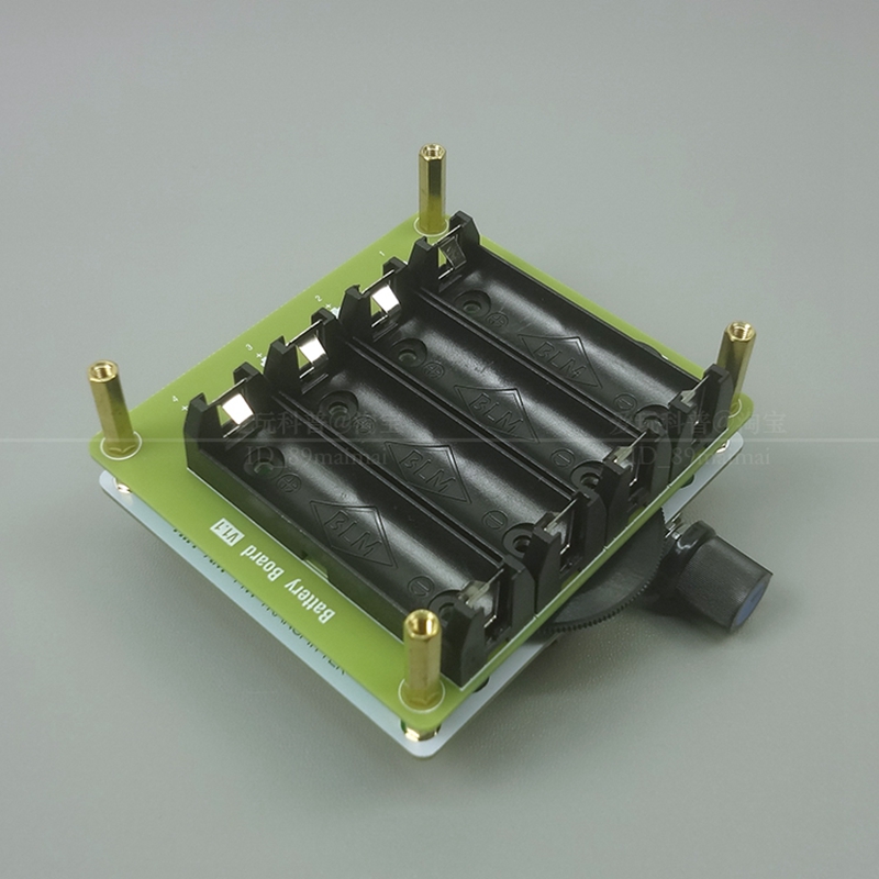
- It can be connected to an external power supply or installed with a battery for independent use.
Specification:
- Frequency range: 525~1605kHz
- Power supply voltage: 6V
- Circuit board size: 78mmx85mm (length × width)
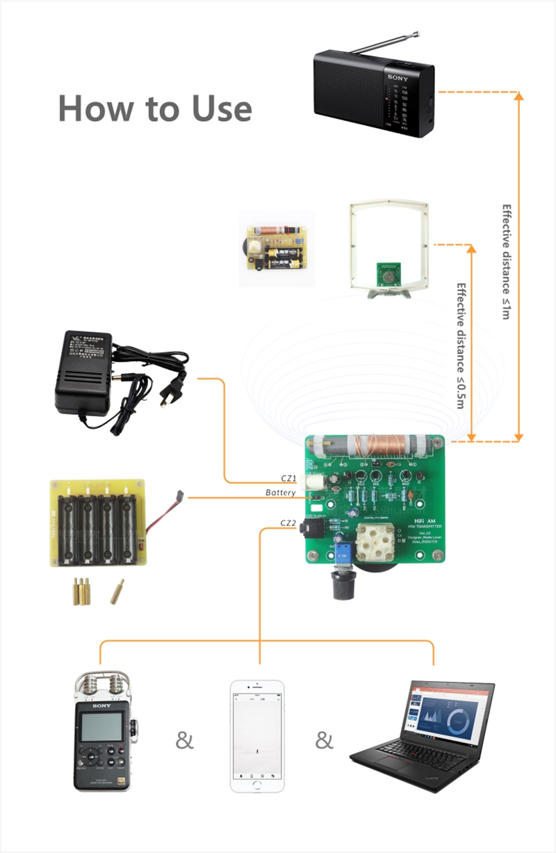
- Transmission distance: about 1 meter for superheterodyne medium wave radios, about 0.5 meters for direct and ore radios
Attention:
Version description:
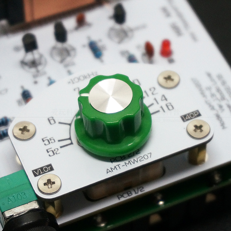
- V1.3 is a modified version of V1.2, which uses a beautiful flat magnetic rod and adds a dial. The calibration scheme comes from the radio with 223P variable capacitor. It is tested that there is a slight error. Players with high requirements can use digital display radio to correct.
Defects description:
- Due to the asymmetry of both sides of the circuit board (especially the single panel), there will be slight natural bending, which has no impact on normal use. There may be some scratches, dust and washing marks on the base surface and copper foil surface;
- Because PCB manufacturers mainly produce multilayer boards (double-sided boards and multilayer boards), they are not familiar with the characteristics of single panel for amateur DIY, and often treat the single panel as a multilayer board to metallize the hole wall. Generally, a single panel does not need to metallize the hole wall, but if there is a metallized hole wall, it is not a fatal error and will not have any impact on the normal operation of the circuit. Only when welding components, greater welding power is required and the temperature of the soldering iron should be increased;
- The copper foil of the circuit board and the board base are bonded by adhesive. If the copper foil is welded for a long time, repeatedly and repeatedly, the copper foil will fall off;
- Some of the organic film variable capacitors have been stored for a long time, the shell has a gray layer, and the lead has oxidation, which can be treated slightly without affecting the use;
- Common ceramic chip capacitor (Y5V, etc.): ceramic chip capacitor (capacity>300pF) has a large error, the nominal error can reach+80% - 20%, the temperature stability is poor, and it is suitable for occasions with low requirements such as filtering and coupling;
- The antenna magnetic rod is slightly bent, and the larger the size is, the more obvious it is, but it has no effect on the service performance. The magnetic rod of the antenna is very fragile and will break when hit.
Restrictions on Use:
- This product has good effect only within the desktop range. When the radio is too far away from the transmitter (more than 1 m), the effect will decrease seriously, which is shown by low sound and deterioration of the signal to noise ratio.
- Increasing the power supply voltage can make the waveform amplitude increase a lot, but the actual available transmission distance does not change much.
- The potentiometer of the transmitter controls the modulation system. If the modulation is too large, the radio demodulation will be distorted, and the waveform of the transmitter itself will also become worse. The correct use is to summarize a suitable position after many times of use, so that the modulation system can be as large as possible and the sound quality can be guaranteed as much as possible. You can turn to this position every time you use it. Do not adjust it frequently as the volume potentiometer of the radio.
- We strongly requires players to abide by the national radio management regulations, rationally practice science and technology, and do not try to use the external power amplifier of this equipment to increase the transmission distance, otherwise the legal consequences arising therefrom will be borne by the implementer himself.
Package Included:
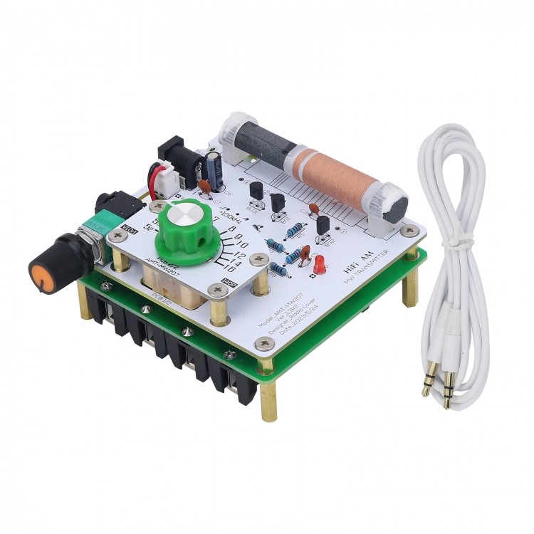
- 1 x Transmitter
- 1 x 3.5mm Headphone Signal Cable
Note:
- Battery is not included.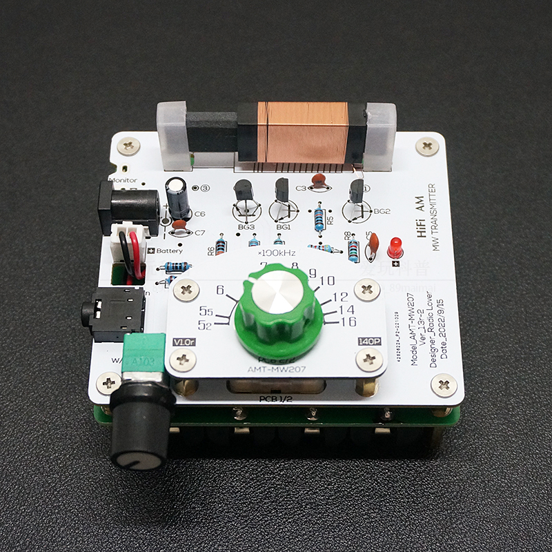


 to Test Crystal Radio Receivers")


